EasyManua.ls Logo

Sony MDS-JE440 - Md Player User Manual

Sony MDS-JE440 - Md Player
64 pages
To Next Page IconTo Next Page
Page #1 background imageLoading...
Page #1 background image
MDS-JE440
SPECIFICATIONS
SERVICE MANUAL
MINIDISC DECK
Model Name Using Similar Mechanism NEW
MD Mechanism Type MDM-7A
Optical Pick-up Type KMS-260B/J1N
US Model
Canadian Model
AEP Model
UK Model
E Model
Australian Model
US and foreign patents licensed form Dolby Laboratories
Licensing Corporation.
Inputs
Outputs
System
MiniDisc digital audio system
Disc
MiniDisc
Laser
Semiconductor laser (
λ
= 780 nm)
Emission duration: continuous
Laser output
MAX 44.6 µW
1)
1) This output is the value
measured at a distance of
200 mm from the objective lens
surface on the Optical Pick-up
Block with 7 mm aperture.
Laser diode
Material: GaAlAs
Revolutions (CLV)
400 rpm to 900 rpm
Error correction
ACIRC (Advanced Cross Interleave
Reed Solomon Code)
Sampling frequency
44.1 kHz
Coding
ATRAC (Adaptive TRansform
Acoustic Coding)/ATRAC 3
Modulation system
EFM (Eight-to-Fourteen
Modulation)
Number of channels
2 stereo channels
Frequency response
5 to 20,000 Hz ±0.3 dB
Signal-to-noiseratio
Over 96 dB during play
Wow and flutter
Below measurable limit
ANALOG IN
Jack type: phono
Impedance: 47 k
Rated input: 500 mVrms
Minimum input: 125 mVrms
DIGITAL IN
Connector type: square optical
Impedance: 660 nm (optical wave
length)
ANALOG OUT
Jack type: phono
Rated output: 2 Vrms (at 50
k)
Load impedance: over 10 k
DIGITAL OUT
Connector type: square optical
Rated output: –18 dBm
Load impedance: 660 nm (optical
wave length)
— Continued on next page —
Question and Answer IconNeed help?

Do you have a question about the Sony MDS-JE440 - Md Player and is the answer not in the manual?

Sony MDS-JE440 - Md Player Specifications

General IconGeneral
BrandSony
ModelMDS-JE440 - Md Player
CategoryStereo System
LanguageEnglish

Summary

SPECIFICATIONS

Technical Specifications List

Detailed technical specifications for the MDS-JE440 MiniDisc deck.

General Information

Power and Supplied Accessories

Details on power specifications and included items.

SELF-DIAGNOSIS FUNCTION

Error Codes and Remedies

Describes error codes and their corresponding causes and remedies.

Error History Display Mode Procedure

Step-by-step guide for using the error history display mode.

Service Notes and Precautions

Safety Check-out Procedures

Essential safety checks after service, focusing on AC leakage.

Handling Optical Pick-up & Laser Diode

Precautions for handling the optical pick-up and laser diode safely.

Component Replacement and Repair Notes

Guidelines for chip component replacement and flexible circuit board repair.

BD Board Waveform Jig

Pre-Repair Checks and Reset

Checks Prior to Parts Replacement

Guidance on checks before replacing components.

Forced Reset Procedure

Steps to perform a forced reset of the system microprocessor.

General Unit Information

Unit Controls and Indicators

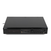
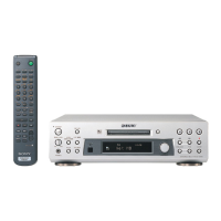
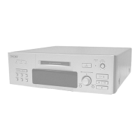
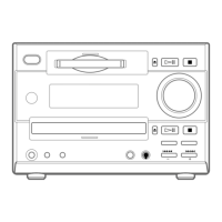
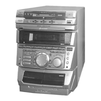
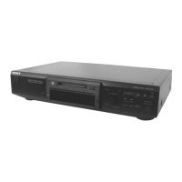
Identifies and explains the function of various buttons and indicators on the unit.

Disassembly Procedures

Upper Case and Front Panel Disassembly

Procedures for removing the upper case and front panel sections.

Main Board and Mechanism Disassembly

Steps for disassembling the main board, PT/VOL-SEL, mechanism deck, and BD board.

Test Mode Operations

Test Mode Precautions and Setup

Precautions for using test modes and methods for setting them up.

Basic Operations, Displays, and Exiting

Explains button functions, displays, and how to exit test modes.

Continuous Playback/Recording and Mode Meanings

Procedures for continuous modes and meanings of various displays.

Electrical Adjustments

Parts Replacement and Adjustment Flow

Flowchart for checks before replacing parts and suspected faulty components.

Adjustment Procedures and Precautions

Crucial precautions, tools, and sequence for performing adjustments.

Specific Adjustment Details (Laser, Traverse, Focus)

Detailed steps for laser power, traverse, focus bias, and error rate adjustments.

Diagrams and Waveforms

Circuit Board Locations and Block Diagrams

Identifies board locations and illustrates functional blocks of the BD section.

Printed Wiring Boards and Schematics

Shows layout of PWB and provides detailed schematic diagrams.

IC Block Diagrams and Pin Functions

Visual representations of IC internal structures and pin function lists.

Exploded Views

Chassis and Front Panel Exploded Views

Visual breakdown of the chassis and front panel components.

Mechanism Section Exploded Views

Exploded views of the MDM-7A mechanism sections.

Electrical Parts List

BD and Main Board Components

Detailed list of components for the BD and main boards.

PT, Vol-Sel Boards, Misc. Parts & Accessories

List of components for PT/Vol-Sel boards, miscellaneous items, and accessories.

Related product manuals