Do you have a question about the Sony MHC-2600 and is the answer not in the manual?
AC power input voltage and frequency for different models.
Power usage details for various models.
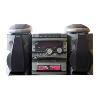
Physical dimensions of the equipment.
Specifies the weight of the units.
Lists included accessories and packing materials.
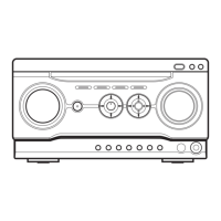
Identifies and describes the unit's controls.
Safety precautions before performing mechanical adjustments.
Details torque specifications for mechanical adjustments.
Information about test tapes used for adjustments.
Procedure for adjusting the record/playback head azimuth.
Procedure for adjusting tape speed.
Details pin functions for IC351 and IC406.
Provides a block diagram of the system.
Shows printed wiring board layout for the main section.
Presents the schematic diagram for the main section.
Provides schematic diagrams for various sections.
Shows printed wiring board layout for the pin jack section.
Illustrates block diagrams for various ICs.
Details pin functions for IC501.
Exploded view of the chassis section.
Exploded view of the mechanism section, part 1.
Exploded view of the mechanism section, part 2.
Electrical parts list for the main board.
Electrical parts list for the panel board.
Electrical parts list for the pin jack board.
Electrical parts list for the power board.
Electrical parts list for the transformer board.
Electrical parts list for the display board.
Procedure for checking RF signal level.
Procedure for checking S curve waveform.
Procedure for checking E-F balance.
Describes traverse oscilloscope waveform observation.
Procedure for checking RF PLL free-run frequency.
Provides a block diagram of the system.
Shows lead layouts for semiconductors.
Illustrates printed wiring boards.
Presents schematic diagrams for various sections.
Illustrates block diagrams for various ICs.
Details pin functions for IC201 and IC401.
Exploded view of the chassis section.
Exploded view of the CD mechanism section.
Exploded view of the optical pick-up block.
List of capacitors with part numbers and specifications.
List of connectors with part numbers.
List of diodes with part numbers and types.
List of transistors with part numbers and types.
List of resistors with part numbers and values.
Procedure for performing leakage tests.
Steps for removing the upper case, front panel, and panel board.
Steps for removing back panel, speaker, jack boards, and fan motor.
Shows the location of various circuit boards.
Shows lead layouts for semiconductors.
Illustrates printed wiring boards for the main section.
Presents the schematic diagram for the main section.
Presents the schematic diagram for the panel section.
Exploded view of the chassis section.
Electrical parts list for audio components.
Electrical parts list for panel components.
Electrical parts list for connector components.
Information on power supply for servicing.
Procedure for checking timer function.
Note on completing service procedures.
Procedure for checking FL tube and key input.
Steps for forcefully turning the unit ON.
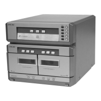
Identifies various parts of the unit.
Instructions for setting the clock.
Instructions for radio operation.
Procedure for storing radio stations.
Procedure for tuning to a preset station.
Procedure for adjusting AM tuning level.
Provides a block diagram of the tuner.
Shows lead layouts for semiconductors.
Illustrates printed wiring boards for the tuner section.
Presents the schematic diagram for the tuner section.
Illustrates printed wiring boards for the display section.
Presents the schematic diagram for the display section.
Exploded view of the chassis section.
Lists hardware items used in assembly.
| Brand | Sony |
|---|---|
| Model | MHC-2600 |
| Category | Stereo System |
| Language | English |