Do you have a question about the Sony MHC-790 and is the answer not in the manual?
Precautions for handling the optical pick-up block to prevent electrostatic breakdown.
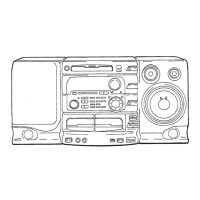
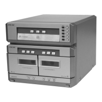
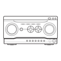
Refers to pages for using controls and lists controls by function and location.
Step-by-step procedure for removing the CD mechanism from the unit.
Step-by-step procedure for removing the TC (Tape Cassette) mechanism.
Precautions and procedures for mechanical adjustments like torque and tape tension.
Procedures for electrical adjustments like tape speed and playback level.
Procedure for adjusting the record bias level for optimal recording performance.
Procedure to adjust the FM tuning indication lighting level.
Procedure for adjusting the focus bias on the CD section.
Notes that this adjustment is not critical and has margin.
Details pin functions and descriptions for IC101.
Details pin functions and descriptions for IC110.
Details pin functions and descriptions for IC501.
Illustrates the block diagram for the CD section of the unit.
Illustrates the block diagram for the main section of the unit.
Provides the schematic diagram for the panel section of the unit.
Shows the printed wiring board layouts for the BD section.
Shows the printed wiring board layouts for the audio section.
Provides the schematic diagram for the audio section of the unit.
Illustrates IC block diagrams for the main section of the unit.
Exploded view of the chassis section showing component parts.
Exploded view of the front panel section-1, listing component parts.
Exploded view of the front panel section-2, listing component parts.
Exploded view of the TC mechanism section-1, listing component parts.
Exploded view of the TC mechanism section-2, listing component parts.
Exploded view of the CD mechanism section-1, listing component parts.
Exploded view of the CD mechanism section-2, listing component parts.
Lists electrical components for the audio board, including capacitors, transistors, and resistors.
Lists components for the BD CD-LED section, including ICs, transistors, resistors, and switches.
Lists components for the HP/MIC section, including capacitors, ICs, jacks, coils, and resistors.
Lists components for HP/MIC, Karaoke, Leaf SW, and Loading sections.
Lists electrical components for the main board, including capacitors, ICs, and connectors.
Continues listing electrical components for the main board, including diodes and transistors.
Lists front end components, ICs, and transistors for the main board.
Lists various resistors for the main board, categorized by resistance value.
Continues the list of resistors for the main board.
Lists remaining components for the main board, including variable resistors, relays, transformers, and terminals.
Continues the parts list for AMS Encoder Panel Power.
Lists components for the Power TC-SW section, including resistors, switches, and diodes.
Lists components for the Transformer Board, including connectors, fuses, and accessories.
| Bluetooth | No |
|---|---|
| CD Player | Yes |
| FM Radio | Yes |
| AM Radio | Yes |
| Karaoke | Yes |
| Equalizer | Yes |
| Speaker Type | 2-way |
| Type | Mini Hi-Fi Component System |