EasyManua.ls Logo

Sony MHC-V02 Service Manual

Sony MHC-V02
38 pages
To Next Page IconTo Next Page
Page #1 background imageLoading...
Page #1 background image
SERVICE MANUAL
Sony Corporation
Published by Sony EMCS (Malaysia) PG Tec
US Model
Canadian Model
AEP Model
UK Model
E Model
Australian Model
MHC-V02
HOME AUDIO SYSTEM
9-890-699-01
2019C80-1
©
2019.03
Ver. 1.0 2019.03
SPECIFICATIONS
Model Name Using Similar Mechanism ZS-RS80BT
Optical Pick-up Name EM101UBS WITH PWB, MOTOR
Note:
Be sure to keep your PC used for service and
checking of this unit always updated with the
latest version of your anti-virus software.
In case a virus aff ected unit was found during
service, contact your Service Headquarters.
Continued on next page
AUDIO POWER SPECIFICATIONS
POWER OUTPUT AND TOTAL HARMONIC
DISTORTION:
(US models only)
Left/Right Channel:
With 5 ohm loads, both channels driven, from 700 Hz – 20,000 Hz;
rated 6 watts per channel minimum RMS power at stereo mode,
with no more than 0.7% total harmonic distortion from 250
milliwatts to rated output.
Speaker section
Speaker system:
2-way, Bass Reflex
Speaker unit:
Tweeter L/R: 40 mm (1 5/8 in), cone type
Woofer: 180 mm (7 1/8 in), cone type
Inputs
AUDIO IN L/R:
Voltage 2 V, impedance 47 kilohms
MIC/GUITAR:
Sensitivity 1 mV, impedance 10 kilohms
(When guitar mode is turned off .)
Sensitivity 200 mV, impedance 1 Megaohm
(When guitar mode is turned on.)
Disc player section
System:
Compact disc and digital audio system
Laser Diode Properties
Emission Duration: Continuous
Laser Output*: Less than 44.6 μW
* This output is the value measurement at a distance
of 200 mm from the objective lens surface on the
Optical Pick-up Block with 7 mm aperture.
Frequency response:
20 Hz – 20 kHz
USB section
Supported USB device:
Mass Storage Class
Maximum current:
1 A
(USB) port:
Type A
FM tuner section (Except AEP, UK)
FM stereo, FM superheterodyne tuner
Antenna:
FM lead antenna
Tuning range:
87.5 MHz – 108.0 MHz (50 kHz step) (Except US)
87.5 MHz – 108.0 MHz (100 kHz step) (US model)
BLUETOOTH section
Communication system:
BLUETOOTH Standard version 4.2
Output:
BLUETOOTH Standard Power Class 2
Maximum output power:
<9.5 dBm
Maximum number of devices to be registered:
8 devices
Maximum number of simultaneous connection
(Multipoint):
3 devices
Maximum communication range:
Line of sight approx. 10 m (32 ft)
1)
Frequency band:
2.4 GHz band (2.4000 GHz – 2.4835 GHz)
Modulation method:
FHSS (Freq Hopping Spread Spectrum)
Compatible BLUETOOTH profiles
2)
:
A2DP (Advanced Audio Distribution Profile)
AVRCP (Audio Video Remote Control Profile)
SPP (Serial Port Profile)
Supported codecs:
SBC (Subband Codec)
AAC (Advanced Audio Coding)
LDAC
1)
The actual range will vary depending on factors such
as obstacles between devices, magnetic fields around a
microwave oven, static electricity, reception sensitivity,
antenna’s performance, operating system, software appli-
cation, etc.
2)
BLUETOOTH standard profiles indicate the purpose of
BLUETOOTH communication between devices.
Supported audio formats
Supported bit rate and sampling frequencies:
MP3:
32/44.1/48 kHz, 32 kbps –
320 kbps (VBR)
AAC:
8/11.025/16/22.05/32/44.1/48 kHz,
5 kbps – 384 kbps (VBR)
WMA:
8/11.025/16/22.05/32/44.1/48 kHz,
48/64/96/128/160/192 kbps (CBR),
64 kbps – 161 kbps (VBR)
WAV:
8/11.025/12/16/22.05/24/32/44.1/
48 kHz (16 bit)
General
Power requirements:
AC 120 V, 60 Hz (US model)
AC 120 V – 240 V, 50/60 Hz (Except US)
Power consumption:
25 W
Power consumption (at the Power Saving mode):
0.5 W (When “BT STBY” is set to “OFF”.)
2 W* (When “BT STBY” is set to “ON”.)
Dimensions (W/H/D) (Approx.):
281 mm × 500 mm × 306 mm
(11 1/8 in x 19 3/4 in x 12 1/8 in)
Mass (Approx.):
6 kg (13 lb 4 oz)
Operating temperature:
5 °C to 35 °C (41 °F to 95 °F)
* The power consumption of the system will be less than
0.5 W when “BT STBY” is set to “OFF”.
Supplied accessories
Remote control (DC 3 V) (1)
R03 (DC 1.5 V) (size AAA) batteries (2)
FM lead antenna (aerial) (1) (supplied only for
certain areas)
AC power cord (mains lead) (1)
AC plug adaptor* (1) (supplied only for certain
areas)
* This plug adaptor is not for the use in Chile,
Paraguay and Uruguay. Use this plug adaptor in
the countries/regions where it is necessary.
Design and specifications are subject to change without
notice.
SYSSET
2019/02/2822:48:45(GMT+09:00)

Other manuals for Sony MHC-V02

Questions and Answers:

Sony MHC-V02 Specifications

General IconGeneral
Speaker type-
Speaker placementFloor
Built-in amplifierYes
Number of woofer drivers1
Number of tweeter drivers2
TypeHome audio mini system
Control typeButtons, Wireless
Display typeLED
Cassette deckNo
Product colorBlack
Housing materialPlastic
Disc loading typeTop
Number of optical discs1 discs
USB 2.0 ports quantityUSB 2.0 ports have a data transmission speed of 480 Mbps, and are backwards compatible with USB 1.1 ports. You can connect all kinds of peripheral devices to them.
Quantity per pack1 pc(s)
RMS rated power- W
Power sourceAC
Power source typeAC, Battery
Power consumption (standby)0.5 W
Power consumption (typical)25 W
Bluetooth version4.2
ColorationMonochromatic
Bluetooth profilesA2DP, AVRCP, SPP
Illumination locationFront
Analog signal format systemNTSC, PAL
Compatible operating systemsAndroid, iOS
Supported radio bandsNot supported
Recording onUSB
Disc types supportedCD, CD-R, CD-RW
Playback disc formatsCD audio
Audio formats supportedAAC, MP3, WAV, WMA
Volume controlDigital
Weight and Dimensions IconWeight and Dimensions
Depth306 mm
Width281 mm
Height500 mm
Weight6000 g
Woofer diameter180 mm
Tweeter diameter40 mm

Summary

Product Specifications

Audio Power Output

Details audio output power and harmonic distortion for US models.

FM Tuner Details

Covers FM tuning range, antenna requirements, and reception standards.

Bluetooth Connectivity Features

Outlines Bluetooth version, power class, profiles, codecs, and range.

Supported Audio File Formats

Lists MP3, AAC, WMA, WAV formats with bit rates and sampling frequencies.

General Unit Characteristics

Includes power requirements, consumption, dimensions, mass, and operating temperature.

Servicing Notes and Precautions

Unleaded Solder Handling

Guidelines for using and characteristics of unleaded solder in repairs.

Optical Pick-Up Block Care

Precautions for handling optical pick-up blocks to prevent damage.

Laser Diode Emission Safety

Safety instructions for checking laser diode emission to prevent eye hazards.

Disassembly Procedures

Disassembly Flowchart

Step-by-step overview of the unit's disassembly process.

Left and Right Panel Removal

Instructions for safely removing the unit's left and right side panels.

Top Panel and Rear Panel Removal

Guide for disassembling the top panel and rear section.

Motherboard Board Access

Procedure for accessing and removing the main motherboard.

SMPS Board and Bottom Chassis

Steps to remove the SMPS board and bottom chassis assembly.

Front Panel (VITO) Section Removal

Instructions for disassembling the front panel section.

Woofer Speaker (SP3) Removal

Guide for removing the 18cm woofer speaker unit.

Test Modes

Panel Test Mode Operation

Checks display panel, LEDs, model info, and button functionality.

User Reset Procedure

Resets all user settings and preset data to initial conditions.

History Mode Access

How to view important data stored when a protection event occurred.

Cold Reset Function

Resets all user settings to factory defaults for customer return.

Shop Front Demo Mode

Activation and release procedure for the shop display demonstration mode.

Electrical Checks

FM Auto Stop Check

Procedure to verify the FM tuner's auto stop function with signal generator.

Troubleshooting Guides

SMPS Board Diagnostic Flow

Troubleshooting flow for SMPS board voltage output issues.

Amplifier Protection Error Diagnosis

Diagnostic flow for 'PROTECTX' errors related to the amplifier section.

Diagrams and Wiring

Block Diagram: RS Servo & USB

Illustrates the signal paths for the RS Servo and USB interface.

Block Diagram: Main Section

Overview of the main processing and control blocks of the unit.

Block Diagram: Amplifier Section

Shows the signal flow and components within the amplifier stage.

Block Diagram: Panel & Power Supply

Illustrates the panel interface and power supply control blocks.

Block Diagram: SMPS Section

Detailed block diagram of the Switched-Mode Power Supply.

Circuit Board Locations

Visual guide to the physical placement of all circuit boards.

Motherboard PWB: Component Side

Printed wiring board layout showing components on the motherboard.

Panel Board PWB Layout

Printed wiring board layout for the unit's front panel.

SMPS Board PWB Layout

Printed wiring board layout for the SMPS power supply board.

Exploded Views

Left & Right Panel Exploded View

Visual breakdown of parts for the left and right panels.

Rear Panel Exploded View

Visual breakdown of parts for the rear panel section.

Bottom Chassis Exploded View

Visual breakdown of parts for the bottom chassis.

Front Panel Exploded View

Visual breakdown of parts for the front panel assembly.

Speaker Cabinet Exploded View

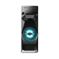
Visual breakdown of parts for the main speaker cabinet.

Top Panel Exploded View

Visual breakdown of parts for the top panel assembly.

Electrical Parts List

Complete Electrical Components List

Comprehensive list of all electrical parts with numbers and descriptions.

Related product manuals