Do you have a question about the Sony MSW-M2100P and is the answer not in the manual?
Reduces risk of fire/electric shock, avoid exposure to rain/moisture, do not open cabinet.
FCC compliance, interference, changes/modifications, shielded interface cables, UL listed cord.
Use approved power cords, proper ratings, consult qualified personnel for questions.
CE marking, EMC Directive, European standards, controlled EMC environment.
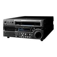
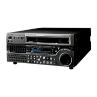
Overview of the MSW-M2100 series player, its construction, and format compatibility.
Details on MPEG IMX format, 12.65mm tape, MPEG-2 compression, and audio channels.
Describes high-performance heads and dynamic tracking for reliable playback.
High-precision digital processing, ITU-R Rec 601, SMPTE 259M, AES/EBU audio.
Ethernet connectivity for MXF file transfer, communication with network devices.
Details on MPEG-2 intraframe encoding at 50 Mbps for high image quality.
Supports 16-bit/48 kHz digital audio, eight digital and four analog outputs.
SDTI-CP output for transferring MPEG-2 data, audio, and metadata.
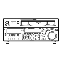
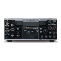
Front panel with wide range of functions and conventional VTR layout.
Conventional VTR layout for basic buttons and jog/shuttle dial operations.
Displays CTL counter, time code, or user bits, edit points, and durations.
Use function keys and MULTI CONTROL knob for settings and menu navigation.
Independent audio level meters and playback level controls for all eight channels.
Smooth, noiseless playback from -1 to +3 times normal speed across formats.
Supports assemble and insert editing, setting edit points, previewing results.
Automatic playback with a varying speed memorized beforehand.
Data reading/writing between cassettes and VTRs for efficient operations.
Control via RS-422A and parallel interfaces, simultaneous control of multiple VTRs.
Optional adaptor for mounting the unit in a standard EIA 19-inch rack.
Conceptual diagrams showing basic and network system configurations.
Diagram showing PC, VTRs, hub, router, and server for network connection.
Installing and starting e-VTR Manager for PC control of the VTR.
License terms for personal/non-commercial use of MPEG-4 Visual Standard.
Prohibition of use for packaged media other than consumer personal use without license.
Identifies the three control panels: Upper, Lower, and Switch panels.
Details the POWER switch, NETWORK button, REMOTE buttons, RS-232C indicator, EJECT button.
Describes the Audio control, CHANNEL CONDITION indicator, Menu control buttons, and Time data display.
Details Memory card slot, Ejection button, CONTROL PANEL connector, PANEL SELECT switch, KEY INHI switch.
Overview of Analog audio, video, digital audio/signal outputs, network, power, and external connectors.
Details analog audio outputs, cue out, reference video inputs, component and composite outputs.
Describes digital audio outputs (AES/EBU) and digital signal outputs (SDTI-CP, SDI).
Details AC IN, ground terminal, and various remote control/interface connectors.
Explains time code output and audio monitor output connectors.
Examples of connecting digital, analog, SDTI-CP, and Ethernet devices.
Diagram showing connections to a digital recorder and video monitor.
Diagram showing connections to analog VTRs for recording audio/video.
Example connections for dubbing video and audio signals via SDTI-CP.
Network connection example for sending video, audio, metadata as MXF files.
Instructions on connecting a reference video signal for output and servo systems.
Overview of basic and extended setup menus for principal operations.
Displaying time code, menu settings, and alarm messages on video output.
Details MPEG IMX cassette types and procedures for inserting/ejecting cassettes.
How to use the red record inhibit plug to prevent accidental shot mark recording.
Instructions for using Memory Stick media for data storage and sharing.
Describes necessary switch and menu settings before starting playback.
Selecting CTL, time code, or user bit values for display.
Information on playing back signals via SDTI-CP output at normal speed.
Details various playback methods: Normal, Jog, Shuttle, Variable Speed, Capstan Override, DMC.
Procedure for starting and stopping normal (x1) speed playback.
Controlling playback speed by turning the search dial.
Controlling playback speed by angular position of the search dial.
Finely controlling playback speed in various ranges.
Temporarily adjusting playback speed for phase synchronization.
Varying playback speed for sections, storing and replaying it.
Procedure for storing playback speed variations for DMC playback.
Methods for starting DMC playback at on-air cue or after preroll.
Describes file transmission using the control panel.
Settings for power switch and NETWORK button before transmission.
Sending video, audio, metadata as MXF files to servers.
Explains shot marks as tape indications for faster cuing.
Describes recording start marks, shot marks 1/2, and post marks.
How the unit reads and stores shot marks from tape into memory.
Unit allows erasing all types, writing only post marks.
Displaying, selecting, and deleting shot marks from a list.
Describes settings for shot mark search type and listing type.
Detailed procedures for reading, writing, and managing shot marks.
Procedure to read in shot marks from a loaded cassette.
How to write a post mark during playback, stop, or search modes.
Displaying the shot mark list, selecting and entering virtual shot marks.
Procedures for cuing up to selected shot marks or adjacent ones.
How to read and display shot data (time, device, shooting info) on the monitor.
Separating and sorting shot marks by cassette in time code sequence.
Describes Tele-File as a non-contact data carrier system for efficient data management.
Data items managed in clips: cue point, write protect, IN/OUT points, etc.
Methods to open the Tele-File menu from function menu or automatically.
Details on reading clip data display, selecting clips and data within clips.
Examples of menu and monitor displays for Tele-File data.
Using clip data to perform preroll and cue up to specific points.
Procedures for modifying clip data, including adding/deleting clips and setting data.
Functions to cancel modifications or resume previous states.
How to display and modify attribute data like title, ID, and write inhibit settings.
Explains UMID (Unique Material Identifier) as meta-data for video/audio materials.
How to output UMIDs on SDI signals and display UMID data on the monitor.
Selecting UMID output type (Basic/Extended) and whether to output UMIDs.
Displaying UMID data in menu section and on video monitor.
Essence marks use term value dictionary items for transferring points.
Outputting essence marks to SDI signals, converting shot marks to essence marks.
Detects video signal changes (cuts, flashes) and converts to essence marks.
Converting detected events to essence marks and recording event marks in Tele-File.
Explains the function menu for frequently made settings and its configuration.
How to change menu item settings, navigate pages, and use function buttons.
Detailed list of function menu items for HOME page and Pages 1-5.
Overview of basic and extended setup menus and their item groups.
Procedures for displaying, customizing, and changing setup menu items.
Details of basic setup menu items like PREROLL TIME, CHARACTER settings, and SYSTEM SELECT.
Details of extended setup menu items for control panels, interfaces, and parameters.
Using the setup utility menu to download, upload, and format Memory Stick media.
Procedures for downloading, uploading, and formatting Memory Stick files.
Procedure for removing cassette when tape slack occurs; requires trained technician.
Instructions for cleaning video and audio heads using a special cleaning cassette.
How error messages are displayed and what they indicate.
Table of error codes, messages, and descriptions for troubleshooting.
Handling moisture condensation and related error messages (ERR-10).
Guidelines for regular checks including Digital Hours Meter and Maintenance Timings.
How to display and use the digital hours meter modes for operational history.
Guideline table for checking and replacing unit components based on hours.
Power requirements, operating temperature, humidity, mass, and dimensions.
Details on tape speeds, playback times, search speeds, and recommended tapes.
Sampling frequency, quantization, compression, channel coding, error correction.
Bandwidth, S/N ratio, K factor, differential gain/phase for analog outputs.
Sampling frequency, quantization, wow/flutter, headroom, emphasis for digital audio.
Quantization, frequency response, dynamic range, distortion, crosstalk for analog audio.
MXF D10 and Proxy AV file formats and specifications for network connectivity.
Speeds and performance metrics for Digital Betacam, Betacam SX, and Analog Betacam playback.
Adjustable ranges for video level, chroma, setup level, Y/C delay, and chroma phase.
Detailed listing of all input, output, and remote control connectors.
Specifications for PC card and Memory Stick slots.
Supplied/optional accessories and advice on preventing electromagnetic interference.
| Video Standard | NTSC / PAL |
|---|---|
| Power Requirements | AC 100-240 V, 50/60 Hz |
| Video Format | Digital |
| Input/Output Connectors | Component |
| Display | LCD |
| Remote Control | Yes |