10
Location and Function of Parts
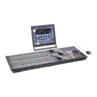
The MVS-6000 system’s center control panel is connected
in the same way to the Ethernet switch to form a network
for exchange of signals between the devices.
This network is used primarily for exchange of various
types of data (key frame effects, snapshots, etc.) and still
pictures of frame memory.
CAUTION
• When you connect the FM DATA connector, DATA
connector, CTRL connector, DME CTRL connector,
and DME DATA connector of the unit to peripheral
devices, use a shielded-type cable to prevent
malfunction due to radiation noise.
• For safety, do not connect the connector for peripheral
device wiring that might have excessive voltage to the
following port(s).
- FM DATA (frame memory data) connector
- CTRL (control) connector
- DATA connector
- DME CTRL (digital multi effect control) connector
- DME DATA (digital multi effect data) connector
Follow the instructions for the above port(s).
* For information about Ethernet switches that can be used in an MVS-6000
system, contact your Sony service representative.
ATTENTION
Par mesure de sécurité, ne raccordez pas le connecteur
pour le câblage de périphériques pouvant avoir une tension
excessive aux ports suivants.
- FM DATA connecteur
- CTRL connecteur
- DATA connecteur
- DME CTRL connecteur
- DME DATA connecteur
Suivez les instructions pour les ports ci-dessus.
VORSICHT
Aus Sicherheitsgründen nicht mit einem Peripheriegerät-
Anschluss verbinden, der zu starke Spannung für diese
Buchse haben könnte.
- Buchse FM DATA
- Buchse CTRL
- Buchse DATA
- Buchse DME CTRL
- Buchse DME DATA
Folgen Sie den Anweisungen für die oben aufgeführten
Buchsen.
For more information about Ethernet switch connectors,
see “MVS-6000 System Configuration” (page 11).
For detailed information about setting up the Ethernet
switch, refer to the documentation supplied with the
switch.
k REF INPUT (reference video input) connectors
(BNC-type)
If you wish to synchronize this unit to an external reference
signal, input the reference signal. For an HDTV system,
input an HD tri-level sync signal, black burst signal, or
analog sync signal. For an SDTV system, input a black
burst signal or analog sync signal.
The two connectors have a loop-through configuration.
Signal input to one connector can be output from the other
connector. If you will not be using the loop-through
output, be sure to terminate the unused connector with the
supplied 75Ω terminator.
l PRIMARY INPUTS 1 to 49 connectors (BNC-type)
These connectors can be used to input up to 49 serial
digital video signals.
The number of these connectors (slots) depends on the
number of MKS-8110G boards that are installed in the
unit.
These connectors allow you to connect with an
MVE-8000A Multi Format DME Processor.
m MONITOR OUT connectors 25 to 32 (BNC-type)
(MKS-8161M)
These are used for auxiliary output to a primary input
monitor or external device. These outputs are useful for
outputting a primary input signal with as little delay as
possible.
n OUTPUTS 1 to 24 connectors (BNC-type)
These connectors output serial digital signals. You can
assign them freely as program output, preview output,
AUX output, and so on.
Outputs 1, 2, 13 to 16 are each constituted by two BNC-
type connectors, and outputs 3 to 12, 17 to 24 are each
constituted by one BNC-type connector.
Make output assignments on the MVS-6000 system center
control panel.
Refer to the User’s Guide for information about signals
that may be assigned.
FC1 and 2 (slot 2) connectors (BNC-type): MVS-6000
(MKS-8450G)
The connectors output signals converted with the format
converter function.
Assign the outputs on the center control panel of the MVS-
6000 system.

 Loading...


