EasyManua.ls Logo

Sony PS-LX431 Service Manual

Sony PS-LX431
26 pages
To Next Page IconTo Next Page
Page #1 background imageLoading...
Page #1 background image
PS-LX430:
US
Model
PS-LX430C:
US
Model
Canadian
Model
PS-LX431:
AEP
Model
UK
Model
E
Model
PS-LX431N:
US
Model
PS-LX433:
US
Model
SPECIFICATIONS
Turntable
Platter
30.0
cm(12
in.),
aluminum-alloy
diecast
Motor
DC
servo
motor
Drive
system
Belt
drive
Controlsystem
DCservocontrol
system
Speed
33!/3
rom,
45
rom
Start-up
time
Comes
to
nominal
speed
within
4/2
rotation
(33/3
rpm)
Wow
and
flutter
0.045%
(WRMS)
Signal-to-noise
ratio
70
dB
(DIN-B)
Automatic
system
Lead-in,
return,
reject,
repeat,
record
size
selection
Suspension
system
High
elasticity
gel
insulator
Toneam
PS-LX430/430C/433:
Type
Statically
balanced
Pivot-to-stylus
length
216.5
mm
(81/2
in.)
Usable
cartridge
Plug-in
type,
6g
Sony
VL-45G
Trackingerror
+3,
—-1
PS-LX431/431N:
Type
Dynamically
balanced
Pivot-to-stylus
length
216.5
mm
(81/,
in.)
Overhang
16.5
mm
(22/39
in.)
Tracking
error
+3,
—-1
SAFETY-RELATED
COMPONENT
WARNING!!
COMPONENTS
IDENTIFIED
BY
SHADING
AND
MARK
A
ON
THE
SCHEMATIC
DIAGRAMS
AND
IN
THE
PARTS
LIST
ARE
CRITICAL
TO
SAFE
OPERATION.
REPLACE
THESE
COMPONENTS
WITH
SONY
PARTS
WHOSE
PART
NUMBERS
APPEAR
AS
SHOWN
IN
THIS
MANUAL
OR
IN
SUPPLEMENTS
PUBLISHED
BY
SONY.
Cartridge
PS-LX430C:
VL-45G
Type
Moving
magnet
type
Frequency
response
20
Hz
to
20
kHz
Channel
separation
20dB
at
1
KHz
Output
voltage
3.5mVat1kHz,5cm/sec.
Loadimpedance
50to
100
kilohms
Tracking
force
1.259
Stylus
Sony
ND-145G
(conical
0.6
mil
diamond)
Weight
6g
PS-LX430/LX433
Not
supplied
PS-LX431:
VL-42G
Type
Moving
magnet
type
Frequency
response
20
Hz
tO
20
kHz
Channel
separation
16dB
at
1
kHz
Output
voltage
2.5
mV
at
1
kHz,
5
cm/sec.
Loadimpedance
=
50to0
100
kilohms
Tracking
force
2g
Stylus
Sony
ND-142G
(conical
0.6
mil
diamond)
Weight
8g
~
Continued
on
page
2
ATTENTION
AU
COMPOSANT
AYANT
RAPPORT
A
LA
SECURITE!
LES
COMPOSANTS
IDENTIFIES
PAR
UNE
TRAME
ET
UNE
MARQUE
A
SUR
LES
DIAGRAMMES
SCHE-
MATIQUES
ET
LA
LISTE
DES
PIECES
SONT
CRITIQUES
POUR
LA
SECURITE
DE
FONCTIONNEMENT.
NE
REM-
PLACER
CES
COMPOSANTS
QUE
PAR
DES
PIECES
SONY
DONT
LES
NUMEROS
SONT
DONNES
DANS
CE
MANUEL
OU
DANS
LES
SUPPLEMENTS
PUBLIES
PAR
SONY.
STEREO
TURNTABLE
SYSTEM
SONY.
Question and Answer IconNeed help?

Do you have a question about the Sony PS-LX431 and is the answer not in the manual?

Sony PS-LX431 Specifications

General IconGeneral
BrandSony
ModelPS-LX431
CategoryTurntable
LanguageEnglish

Summary

Introduction and Model Specifications

Model Variants

Lists different model designations (US, AEP, UK, E) for the PS-LX430/430C/431/431N/433.

General Specifications

Details for turntable, tonearm, and cartridge specifications across models.

Safety Component Warning

Highlights critical components for safe operation and replacement guidance.

General Information and Identification

Power, Dimensions, and Weight

Provides electrical power requirements, physical dimensions, and weights for various models.

Model Identification Labels

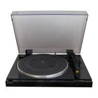
Explains how to identify the unit model using the specification label.

Safety Precautions and Belt Installation

US Model Safety Check-Out

Details AC leakage testing procedures for ensuring safe operation in US models.

Belt Installation Caution

Advises on the correct orientation of the belt during installation for proper function.

Section 1: Outline and Parts

Parts Identification Diagram

Illustrates and labels all mechanical parts of the turntable system.

Anti-Skating Compensator

Explains the function and adjustment of the anti-skating compensator for optimal tracking.

Section 1 Continued: Controls and Block Diagram

Control Panel Functions

Describes the operation of various buttons, switches, and levers on the unit.

System Block Diagram

Visual representation of the internal electronic signal flow and component interconnections.

Section 2: Disassembly Procedures

Basic Component Removal

Step-by-step instructions for removing the motor, S/S SW board, and lamp board.

Section 2 Continued: Board and Tonearm Disassembly

System Control Board Removal

Detailed steps for removing the System Control (A) and (B) boards from the unit.

Tonearm Unit and Chassis Disassembly

Procedures for disassembling the tonearm unit and chassis block.

Section 2 Continued: Installation Procedures

Push Rod and Lifter Lever Installation

Instructions and cautions for installing the push rod and lifter lever assembly.

Section 2 Continued: Index Lever Assembly

Tonearm and Chassis Assembly

Steps for assembling the tonearm unit and chassis block with index levers.

Index Lever Adjustment

Detailed instructions for assembling and adjusting the index levers (B and C).

Section 2 Continued: Arm Lever and Drive Gear Installation

Arm Lever and IFC Knob Installation

Procedures for installing the arm lever and the IFC (anti-skating) knob.

Phono Board and Drive Gear Installation

Steps for installing the phono board and the drive gear assembly.

Tonearm Specific Procedures

Lead Wire Installation (PS-LX431)

Instructions for routing lead wires through the tonearm pipe and center joint for PS-LX431.

Arm Pipe Removal (PS-LX431)

Steps for disassembling the tonearm pipe from the tonearm unit for PS-LX431.

Tonearm Specific Procedures (Cont.)

Lead Wire Installation (PS-LX430/433)

Instructions for routing lead wires through the tonearm pipe and center joint for PS-LX430/433.

Arm Pipe Removal (PS-LX430/433)

Steps for disassembling the tonearm pipe from the tonearm unit for PS-LX430/433.

Section 3: Adjustments Overview

Mechanical Adjustments

Procedures for longitudinal sensitivity, stylus force, and horizontal balance adjustments.

Section 3 Continued: Brake Lever Adjustment

Brake Lever Position Adjustment

Steps to adjust the brake lever position for proper operational contact.

Section 3 Continued: Stylus Height Adjustment

Stylus Height Adjustment Procedures

Detailed steps for adjusting stylus height in both automatic and manual modes.

Section 3 Continued: Stylus Drop-point and Speed Adjustment

Stylus Drop-point Adjustment

Procedure to adjust the stylus drop-point on the record for accurate tracking.

Speed Adjustment

Instructions for adjusting turntable speed (33/45 RPM) using potentiometers.

Section 4: Diagrams

Mounting Diagram

Shows physical layout and mounting positions of components and boards.

Section 4 Continued: Schematic Diagrams

Circuit Schematics

Provides detailed circuit schematics for all major electronic boards of the turntable.

IC Functions

IC102 Pin Functions

Detailed description of the pin functions for the LM6416E-557 microcomputer IC.

Section 5: Exploded Views and Parts Lists

Main Unit Parts Identification

Exploded view and parts list for the main chassis and turntable assembly.

Board and Switch Parts Identification

Exploded views and parts lists for electronic boards and switches.

Lever and Spring Components Identification

Exploded views and parts lists for levers, springs, and small mechanical parts.

Tonearm Parts Identification (PS-LX431)

Exploded view and parts list for the tonearm assembly specific to PS-LX431 models.

Tonearm Parts Identification (PS-LX430/433)

Exploded view and parts list for the tonearm assembly specific to PS-LX430/433 models.

Section 6: Electrical Parts List

Component Listings

Lists of capacitors, resistors, coils, and semiconductors with part numbers.

Section 6 Continued: Electrical Parts and Accessories

Resistors, Switches, and Accessories

Lists of resistors, switches, oscillator, and accessory/packing materials.

Related product manuals