I Pin assignment I
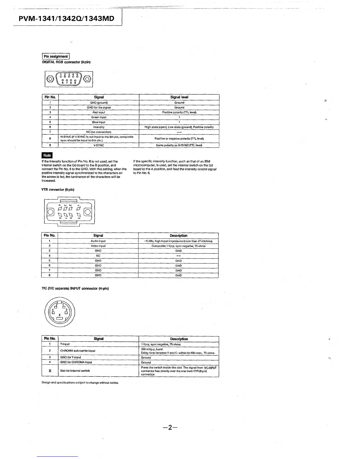
DIGITAL RGB connector (9-pin)
@
Pin No.
1
2
3
4
5
6
7
8
9
-
1 2 3 4 5
0 0 0 0 0
0 0 0 0
6 7 8 9
@
Signal
GND (ground)
GND for the signal
Red input
Green Input
Blue input
Intensity
NC (no connection)
H·SYNC (If V-SYNC Is not Input to the 9th pin, composite
sync should be Input to this pin.)
V-SYNC
If the intensity function of Pin No. 6 is not used, set the
internal switch on the Qd board to the El position, and
connect the Pin No. 6 to the GND. With this setting, when the
positive intensity signal synchronized to the characters on
the screen Is fed, the luminance of the characters will be
increased.
VTR connector (8-pin)
Pin No.
Signal
1
Audio input
2
Vldeoinpur
3 GND
4
NC
5
GND
6
GND
7
GND
8
GND
YIC (YIC separate) INPUT connector (4-pin)
Pin No.
Signal
1
Y-lnput
2
CHROMA sub-carrier-input
3
GND tor Y-input
4
GND tor CHROMA-input
*
Slot for Internal switch
Design and specifications subject to change without notice.
Signal level
Ground
Ground
Positive polarity (TTL level)
I
I
High state (open), Low state (ground), Positive polarity
-
Positive or negative polarity (TTL le11el)
Sarne polarity as H-SYNC (TTL level)
If the specific intensity function, such as that of an IBM
microcomputer, is used, set the internal switch on the Qd
board to the A position, and feed the intensity control signal
to Pin No.6.
Description
-5 dBs, high input impedance (more than 47 kilohms)
Composite 1 Vp-p, sync negative, 75 ohms
GND
-
GND
GND
GND
GND
Description
1 Vp-p, sync negati'le, 75 ohms
300 mVp-p, burst
Delay time bet we.en Y and C: within 0± 100 nsec., 75 ohms
Ground
Ground
Press the switch Inside this slot. The signal from VIC-INPUT
connector has priority over the one from VTA (8-pin)
connector.
-2-