SECTION 5
CIRCUIT ADJUSTMENTS
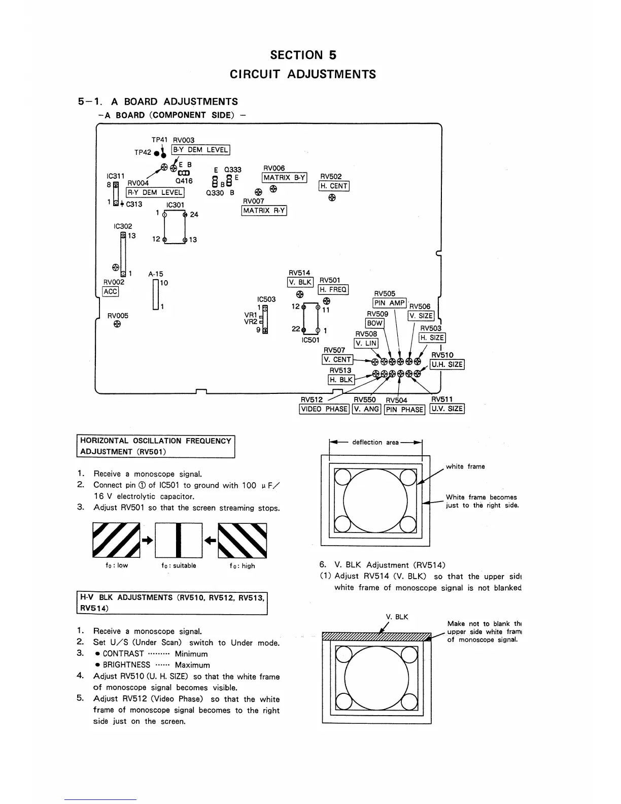
5 - 1. A BOARD ADJUSTMENTS
-A BOARD (COMPONENT SIDE) -
TP41 RV003
TP42e~ IB-Y DEM
LEVELJ
~tE B
Ic311 /
O
CJJ1
16
8~ RV004
E 0333
§ B§ E
RV006
!MATRIX B-YJ
RV502
IH, CENTI
$
I R-Y DEM LEVEL I
1 ' + C313 IC301
IC302
~13
~~1
RV002
IACCI
RV005
$
1024
12 13
A-15
r
0330 B
HORIZONTAL OSCILLATION FREQUENCY
ADJUSTMENT (RV501)
1. Receive a monoscope signal.
$ $
RV007
!MATRIX R-Yj
IC503
VR1
1~
VR2
9
2. Connect pin (j) of IC501 to ground with 100 µ F/
1 6 V electrolytic capacitor.
3. Adjust RV501 so that the screen streaming stops.
fo: low f o : suitable
fo: high
H-V BLK ADJUSTMENTS (RV510, RV512, RV513,
RV514)
1. Receive a monoscope signal.
2. Set U/S (Under Scan) switch to Under mode.
3. • CONTRAST .. .... ... Minimum
• BRIGHTNESS ...... Maximum
4. Adjust RV510 (U. H. SIZE) so that the white frame
of monoscope signal becomes visible.
5. Adjust RV512 (Video Phase) so that the white
frame of monoscope signal becomes to the right
side just on the screen.
RV512 RV550 RV504 RV511
!VIDEO PHASE I Jv. ANGj JPIN PHASE! 1u.v. SIZE!
6. V. BLK Adjustment (RV514)
white frame
White frame becomes
just to the right side.
(1) Adjust RV514 (V. BLK) so that the upper side
white frame of monoscope signal is not blanked
V. BLK
Make not to blank th1
upper sicie white frami
of monoscope signal.