EasyManua.ls Logo

Sony PVM-1444QM User Manual

Sony PVM-1444QM
119 pages
To Next Page IconTo Next Page
Page #1 background imageLoading...
Page #1 background image
SERVICE
MANUAL
AEP
Model
PVM-1440QM
Chassis No.
SCC-C57A-A
PVM-1442QM
Chassis No.
SCC-C56A-A
PVM-1
444QM
Chassis No.
SCC-C55A-A
(PVM-1444QM)
Video
signal
Frequency
response
Line
input:
More than
7
MHz
(-3
dB)
Y/C input:
More
lhan
8
MHz
(-3
dB)
Component
input
(Y/R-Y/B-Y): More
than
8
MHz
(-3
dB)
R.G.B.
input
(analog):
More than
9
MHz
(-3
dB)
Chrominance
subcarrier
attenuation
3.58
MHz: Less
than
-30
dB
(comb
filter)
4.43
MHz: Less
than
-36
dB
(trap
filter)
Bandpass
3.58
MHz:
2
MHz
equiband
4.43 MHz:
2
MHz
equiband
Chrominance/luminance
time
error
Composite: Less
than ±100
ns
Y/C
Video: Less
than
±50
ns
Component:
Less
than
±50
ns
Aperture correction
-4.5
to
+6.5 dB (at
4.5 MHz)
Synchronization
AFC
time
constant:
1 msec
Line
pull
range
Horizontal:
±500
Hz
Vertical:
8
Hz
Picture
performance
Normal
scan
7%
overscan
of
CRT
effective
screen area
Under scan
3%
underscan
of
CRT
effective
screen
area
H.
linearity
error Less
than
4%
V.
linearity
error Less
than
5%
Convergence
Central
area:
0.6
mm
Peripheral
area:
0.8
mm
Raster size
stability
H:
1.0%,
V: 1.5%
High
voltage
regulation
3%
Audio
output
0.6
W
(Max.)
CRT
PVM-1444QM/PVM-1442QM:
EBU
PVM-1440QM:
P-22
Chromacity
coordinates
(EBU
only)
i
X
Y
Red
0.640
0.330
Green
0.290
0.600
Blue
1
0.150
0.060
(tolerance
±0.01)
Color
temperature
6,500° K/9,
300°
K
(+8MPCD),
selectable
AC
regulation
range
220
-
240
V AC,
50/60
Hz
Power
consumption
Approx.
75
Wh
SPECIFICATIONS
inputs
For
ail
models
VIDEO
IN:
BNC
connector
AUDIO
IN: phono
jack
VTR: 8-pin
connector
Y/C-INPUT
VIDEO: 4
pin connector
AUDIO:
phono jack
PVM-1444QM
only
EXT SYNC:
BNC connector
composite sync
1-4
Vp-p,
negative, 75
ohms
terminated,
automatically
released
when cable
is
connected
to
the output
connector.
ANALOG
RGB/COMPONENT:
BNC
connector
R, G, B
and
Y
channels:
0.7 Vp-p, ±6
dB,
non composite
R-Y and
B-Y
channels: 0.525
Vp-p,
±6 dB
(Standard
color
bar signal of
75-percent
chrominance)
When the
composite
signal
is
fed to
the
G
or
Y
channels,
the
monitor
can
be
activated
in the
internal
sync mode.
75
ohms
terminated,
automatically
released
when a cable is
connected
to the output
connector.
CTRL S:
Minijack
. w.
wokiub
manuals
MAURITRON
SERVICES
8
Cherry
Tree
Road,
Chinnor
Oxfordshire,
OX9
4QY
Tel
(01844) 351694
Fax
(01844) 352554
email:-
mauritron@dial.pipex.com
PVM-1442QM
only
EXT
SYNC: BNC
connector
composite
sync
1-4
Vp-p.
negative, 75
ohms
terminated,
automatically
released
when cable
is
connected to
the output
connector.
ANALOG
RGB: BNC
connector
0.7 Vp-p,
±6 dB,
non
composite
75
ohms
terrrftnated,
automatically
released
when cable
is
connected
to
the
output
connector.
DIGITAL RGB: 9-pin
connector
CTRL S: Minijack
PVM-1440QM
ANALOG
RGB
signal through
AV: 0.7 Vp-p,
±6
dB,
non composite,
75 ohms
terminated
Continued on
next page
TRINITRON
®
COLOR
VIDEO
MONITOR
SONY
Question and Answer IconNeed help?

Do you have a question about the Sony PVM-1444QM and is the answer not in the manual?

Sony PVM-1444QM Specifications

General IconGeneral
Display TypeCRT
Screen Size14 inches
Aspect Ratio4:3
Input ConnectorsBNC, Composite, S-Video
OutputsBNC
AudioYes
Power100-240V AC

Summary

SPECIFICATIONS

AV CONNECTOR AND SAFETY WARNINGS

Critical Safety Precautions

Essential safety warnings for servicing the unit, including use of isolation transformer.

GENERAL FEATURES

LOCATION AND FUNCTION OF CONTROLS

Front Panel Controls

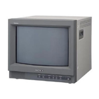
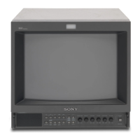
Description of all buttons and indicators on the front panel, including adjustment controls.

REAR PANEL CONNECTOR DESCRIPTIONS

DISASSEMBLY PROCEDURES

DISASSEMBLY: BRACKET AND CONTROL UNIT REMOVAL

PICTURE TUBE REMOVAL AND ANODE CAP ADHERING

SET-UP ADJUSTMENTS: BEAM LANDING

Beam Landing Adjustment Steps

Step-by-step guide for adjusting beam landing.

SET-UP ADJUSTMENTS: CONVERGENCE

Static Convergence Adjustment

Procedure for static convergence on the screen center.

Dynamic Convergence Adjustment

Procedure for dynamic convergence around the screen.

Screen Corner Convergence

Adjusting convergence at the screen corners.

SET-UP ADJUSTMENTS: FOCUS AND SCREEN CORNER ADJUSTMENTS

Focus Adjustment

Steps to achieve optimal focus.

Screen Corner Convergence Adjustment

Affixing permalloy for corner convergence correction.

SET-UP ADJUSTMENTS: WHITE BALANCE

Screen G2 Voltage Adjustment

Adjusting green cathode voltage for white balance.

White Balance Adjustment Procedure

Steps for setting white balance using color bars.

SAFETY RELATED ADJUSTMENTS

HVR Replacement Confirmation

Verifying output voltage after HVR replacement.

R500 Confirmation and Readjustment

Hold-down circuit confirmation and readjustment procedures.

CIRCUIT ADJUSTMENTS: A BOARD

Horizontal Oscillation Frequency Adjustment

Adjusting RV501 for screen streaming.

HV BLK Adjustments

Adjusting RV510, RV512, RV513 for white frame visibility.

V. BLK Adjustment

Adjusting RV514 to prevent blanking of the upper white frame.

CIRCUIT ADJUSTMENTS: A BOARD CONTROLS

H. BLK Adjustment

Blanking the vertical line of the white frame.

Screen Phase Adjustment

Equalizing white frame width on screen sides.

Vertical Deflection Part Adjustments

Adjusting V. SIZE, V. CENT, V. LIN.

Horizontal Deflection Part Adjustments

Adjusting H. CENT, H. SIZE, PIN AMP, PIN PHASE, V. ANG, BOW.

CIRCUIT ADJUSTMENTS: DELAY AND LEVEL ADJUSTMENTS

V. DELAY Adjustment

Adjusting IC503 VR2 for 8.1 msec.

ACC Adjustment

Adjusting RV002 for burst signal level.

B-Y Dem Level Adjustment

Adjusting RV003 for B-Y waveform.

R-Y Dem Level Adjustment

Adjusting RV004 for R-Y waveform.

CIRCUIT ADJUSTMENTS: MATRIX AND COLOR SYNCHRONIZATION

Matrix Adjustment

Adjusting RV006, RV007 for flat waveforms.

XA Board Adjustment

Adjustments for the XA board.

Color Synchronization Adjustments

Adjusting CV3 for 3.58 MHz and CV4 for 4.43 MHz.

CIRCUIT ADJUSTMENTS: BA BOARD

NTSC 3.58 MHz Adjustment

Adjusting RV292 for BLUE OUT waveform.

PAL Adjustments

Adjusting RV290 for anti-PAL portion.

NTSC 4.43 MHz Adjustment

Adjusting RV291 for BLUE OUT waveform.

CIRCUIT ADJUSTMENTS: BA BOARD COLOR BALANCE

Anti-PAL Adjustment

Adjusting RV290 for flat R-Y anti-PAL portion.

SECAM Adjustments

Adjusting T401, L403, L405 for SECAM signals.

Color Balance Adjustment

Adjusting L403 for non-colored portion level.

DIAGRAMS: FRAME SCHEMATIC

DIAGRAMS: BLOCK DIAGRAMS

DIAGRAMS: BLOCK DIAGRAMS (Continued)

PRINTED WIRING BOARDS: A BOARD

PRINTED WIRING BOARDS: A BOARD (Continued)

SCHEMATIC DIAGRAMS: KEY BOARDS

SCHEMATIC DIAGRAMS: KEY BOARDS (Continued)

EXPLODED VIEWS: CHASSIS

EXPLODED VIEWS: PICTURE TUBE

ELECTRICAL PARTS LIST: COMPONENT CATEGORIES

Resistors and Capacitors

List of resistors and capacitors used in the monitor.

ELECTRICAL PARTS LIST: COMPONENT CATEGORIES (Continued)

ICs, Transistors, and Variable Resistors

List of integrated circuits, transistors, and variable resistors.

Resistors, Switches, and Capacitors

List of resistors, switches, and capacitors.

Capacitors, Diodes, ICs, and Transistors

List of capacitors, diodes, ICs, and transistors.

Transistors and Resistors

List of transistors and resistors.

Resistors

List of resistors.

Components by Type

Comprehensive list of various component types.
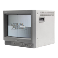
ELECTRICAL PARTS LIST: SEMICONDUCTORS

ELECTRICAL PARTS LIST: SEMICONDUCTORS (Continued)

ELECTRICAL PARTS LIST: COMPONENT LISTS

ELECTRICAL PARTS LIST: COMPONENT LISTS (Continued)

ELECTRICAL PARTS LIST: RESISTOR LIST

ELECTRICAL PARTS LIST: RESISTOR LIST (Continued)

ELECTRICAL PARTS LIST: RESISTOR AND CONNECTOR LISTS

ELECTRICAL PARTS LIST: MISCELLANEOUS AND ACCESSORIES

Related product manuals