Do you have a question about the Sony RDR-HX680 and is the answer not in the manual?
Details about laser, channel coverage, signal reception, timers, and recording formats.
Lists various connectors for audio, video, digital signals, and USB.
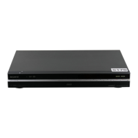
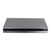
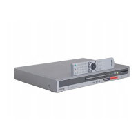
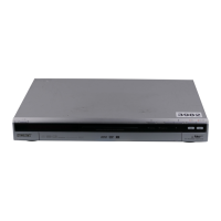
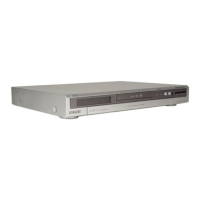
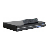
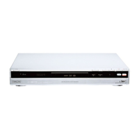
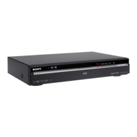
Covers power, dimensions, HDD capacity, operating environment, and accessories.
Critical warning about laser proximity during servicing to avoid eye hazard.
Properties and handling guidelines for unleaded solder.
Instructions for handling components with confidential information.
Troubleshooting guide for common HDD errors and recognition issues.
Procedure for removing the top cover of the unit.
Steps for disassembling the tray cover assembly.
Guide to disassembling the front panel assembly.
Steps to remove the FR-291 and FL-184 circuit boards.
Instructions for disassembling the DVD drive unit.
Procedure for removing the DC fan.
Steps for disassembling the hard disk drive unit.
Guide to disassembling the AV-133/134 circuit boards.
Steps for disassembling the switching regulator.
Identifies the location of various circuit boards within the unit.
High-level block diagram for specific AEP, UK, RUS models.
High-level block diagram for specific AUS, TH, SP, CND models.
Detailed block diagram of the AV-133 board for AEP models.
Detailed block diagram of the AV-134 board for non-AEP models.
Detailed block diagram of the RD-066 board.
Block diagram for FR-291, FL-184, and VDC-001 boards.
Diagram illustrating the power supply block of the unit.
Overall schematic diagram showing interconnections between major blocks.
Schematic for AV-133 board, IT controller and IR functions.
Schematic for AV-133 board, power and fan control.
Schematic for AV-133 board, video and audio circuits.
Schematic for AV-133 board, EURO specific settings.
Schematic for AV-133 board, tuner section.
Schematic for AV-134 board, IT controller and IR functions.
Schematic for AV-134 board, power and fan control.
Schematic for AV-134 board, video and audio circuits.
Schematic showing the jack connections for AV-134 board.
Schematic for AV-134 board, tuner section.
Schematic for FR-291 board related to FL driver, line 2 input.
Schematic for FL-184 board, DV, USB, remote, power functions.
Schematic of the power block for the RD-066 board.
Schematic of the EMMA block for the RD-066 board.
Schematic of the video/audio block for the RD-066 board.
Schematic of the memory block for the RD-066 board.
Schematic of the SATA/IDE interface for the RD-066 board.
Schematic of the HDMI, DV, USB blocks for the RD-066 board.
Schematic of the DVD drive for the RD-066 board.
Schematic of the SRV-2101EK switching regulator.
Schematic of the SRV-2058EK switching regulator.
Schematic of the SRV-2059WW switching regulator.
Printed wiring board layouts for various boards.
Printed wiring board for FR-291, FL driver and line 2 input.
Printed wiring board for AV-133, covering multiple functions.
Printed wiring board for AV-134, covering multiple functions.
Printed wiring board for RD-066, covering multiple blocks.
Printed wiring board for FL-184, covering DV, USB, remote, power.
Pin function details for the IT Control IC on AV-133/134 boards.
Pin function details for the AV Encoder/Decoder IC on the RD-066 board.
Lists required equipment for service, including monitor and remote.
Flowchart showing how to navigate through the service modes.
Procedures for accessing diagnostic functions.
Menu for configuring unit settings and firmware.
Adjusts video output levels and S-video signals for proper display.
Checks and adjusts the video output signal level.
Verifies S-Video Y-signal output amplitude.
Confirms S-Video S-C signal conformity to PAL standard.
Checks the component Y signal output amplitude.
Confirms B-Y signal conformity to PAL/NTSC standards.
Confirms R-Y signal conformity to PAL/NTSC standards.
Checks Scart video output level against PAL standard.
Confirms Scart Y-signal output rating.
Confirms Scart S-C signal conformity to PAL standard.
Confirms RGB R signal output level for Scart input.
Confirms RGB G signal output level for Scart input.
Confirms RGB B signal output level for Scart input.
Visual diagrams of parts with reference numbers.
Exploded view of the main unit showing overall assembly.
Exploded view of the chassis and internal components.
List of electrical components with part numbers and specifications.
| Audio formats supported | MP3 |
|---|---|
| Video formats supported | DIVX |
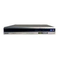
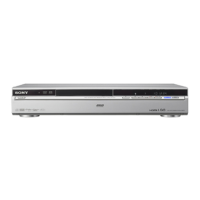
| Device type | DVD recorder |
| Plug and Play | Yes |
| Product color | Silver |
| DVD region code | 2 |
| Disc loading type | Tray |
| HDD capacity | 120 GB |
| Maximum HDD recording time | 340 h |
| Disc types supported | DVD-RAM |
| Composite video out | 1 |
| USB 2.0 ports quantity | USB 2.0 ports have a data transmission speed of 480 Mbps, and are backwards compatible with USB 1.1 ports. You can connect all kinds of peripheral devices to them. |
| Dimensions (WxDxH) | 430 x 286 x 66.5 mm |
| Power consumption (typical) | 44 W |
| Weight | 4400 g |
|---|