EasyManua.ls Logo

Sony RDR-HX750 Service Manual

Sony RDR-HX750
157 pages
To Next Page IconTo Next Page
Page #1 background imageLoading...
Page #1 background image
SERVICE MANUAL
DVD RECORDER
SPECIFICATIONS
RDR-GX350/HX650/
HX750/HX950
RMT-D245P/D246P/D247P
AEP Model
RDR-GX350/HX650/HX750/HX950
UK Model
RDR-GX350/HX750
Russian Model
RDR-GX350/HX750/HX950
Photo: RDR-HX750
RMT-D247P
(GX350/HX650)
(HX750/HX950) (HX750/HX950)
System
Laser: Semiconductor laser
Channel coverage:
PAL/SECAM (B/G, D/K, I, L)
VHF: E2 to E12, R1 to R12, F2 to F10,
Italian A to H, Ireland A to J, South
Africa 4 to 11, 13
UHF: E21 to E69, R21 to R69, B21 to
B69, F21 to F69
CATV: S01 to S05, S1 to S20, France
B to Q
HYPER: S21 to S41
The above channel coverage merely ensures
the channel reception within these ranges. It
does not guarantee the ability to receive
signals in all circumstances. For details, see
“Receivable channels”.
Video reception: Frequency synthesizer
system
Audio reception: Split carrier system
Aerial out: 75-ohm asymmetrical aerial
socket
Timer: Clock: Quartz locked/Timer
indication: 24-hour cycle (digital)/
Power back-up duration: 1 hour
Video recording format: MPEG-2,
MPEG-1
Audio recording format/applicable
bit rate: Dolby Digital 2 ch
256 kbps/128 kbps (in EP, SLP, and
SEP mode), PCM
Inputs and outputs
LINE 2 OUT
(AUDIO): Phono jack/2 Vrms/10 kilohms
(VIDEO): Phono jack/1.0 Vp-p
(S VIDEO): 4-pin mini DIN/Y: 1.0 Vp-p,
C: 0.3 Vp-p (PAL)
LINE 2 IN
(AUDIO): Phono jack/2 Vrms/more than
22 kilohms
(VIDEO): Phono jack/1.0 Vp-p
(S VIDEO): 4-pin mini DIN/Y: 1.0 Vp-p,
C: 0.3 Vp-p (PAL)
LINE 3 – TV: 21-pin
CVBS OUT
S-Video/RGB OUT (upstream)
LINE 1/DECODER: 21-pin
CVBS IN/OUT
S-Video/RGB IN
Decoder
DV IN:
4-pin/i.LINK S100
DIGITAL OUT (COAXIAL): Phono jack/
0.5 Vp-p/75 ohms
COMPONENT VIDEO OUT
(Y, P
B
/C
B
, P
R
/C
R
):
Phono jack/Y: 1.0 Vp-p,
P
B
/C
B
: 0.7 Vp-p, P
R
/C
R
: 0.7 Vp-p
G-LINK:
mini jack
HDMI OUT: HDMI 19-pin-Standard
Connector
USB:
USB jack Type A (For connecting
digital still camera, Memory card
reader and USB memory)
USB jack Type B (For connecting
PictBridge-compatible printers)
General
Power requirements: 220-240 V AC,
50/60 Hz
Power consumption:
Dimensions (approx.):
4
RDR-GX350: 22 W
RDR-HX650: 40 W
RDR-HX750/HX950: 44 W
30 × 66.5 × 286 mm (width/height/
depth) incl. projecting parts
Hard disk drive capacity:
RDR-HX650/HX750: 160 GB
RDR-HX9
RDR-HX750: AEP, UK/HX950: AEP, UK:
RDR-HX750/HX950:
RDR-HX750/HX950:
50: 250 GB
Mass (approx.):
RDR-GX350 : 3.6 kg
RDR-HX650/HX750/HX950: 4.4 kg
RDR-HX750/HX950:
Operating temperature: 5°C to 35°C
Operating humidity: 25% to 80%
Supplied accessories:
Mains lead (1)
Aerial cable (1)
Remote commander (remote) (1)
Set top box controller (1)
R6 (size AA) batteries (2)
Specifications and design are subject to
change without notice.
Ver. 1.2 2007.10
Revised-2
w
w
w
.
x
i
a
o
y
u
1
6
3
.
c
o
m
Q
Q
3
7
6
3
1
5
1
5
0
9
9
2
8
9
4
2
9
8
T
E
L
1
3
9
4
2
2
9
6
5
1
3
9
9
2
8
9
4
2
9
8
0
5
1
5
1
3
6
7
3
Q
Q
TEL 13942296513 QQ 376315150 892498299
http://www.xiaoyu163.com

Table of Contents

Other manuals for Sony RDR-HX750

Question and Answer IconNeed help?

Do you have a question about the Sony RDR-HX750 and is the answer not in the manual?

Sony RDR-HX750 Specifications

General IconGeneral
TypeDVD Recorder
Hard Drive Capacity250 GB
Hard DriveYes
Video FormatMPEG-2
Dimensions430 x 360 x 60 mm
Weight3.5 kg
TV TunerYes
Playback FormatsDVD, CD, MP3, JPEG
Recording FormatDVD-R, DVD-RW, DVD+R, DVD+RW
Audio FormatDolby Digital
Input/OutputComposite, S-Video, HDMI
Audio DAC24-bit
Output Resolution1080i

Summary

Service Manual

Specifications

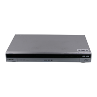
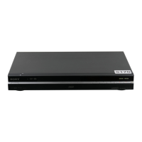
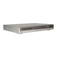
Detailed technical parameters for the DVD recorder's features and components.

Warnings and Precautions

Safety Warnings

Critical safety instructions to prevent hazards during operation or servicing.

Schematics and Printed Wiring Boards

Schematic Diagrams

Detailed circuit diagrams for various internal boards and components.

HDD Failure Diagnosis

Defective HDD

Symptoms and initial checks for identifying a defective Hard Disk Drive.

Troubleshooting HDD E01

Display [E01] on FLD with unrecognized HDD

Flowchart for diagnosing and resolving the E01 error related to unrecognized HDDs.

Troubleshooting HDD E02 and Freezing

Display [E02] on FLD

Flowchart for diagnosing and resolving the E02 error.

Contents Freeze During Playback

Troubleshooting steps for when playback freezes for video, MP3, or JPG files.

HDD Performance Check

Performance Check

Procedure for testing HDD performance across all sectors without erasing data.

Disc Formatting and GUIDE Plus+

Introduction to the GUIDE Plus+ System

Overview of the GUIDE Plus+ interactive program guide system.

Timer Recording

Timer Recording (GUIDE Plus+/Manual)

Instructions for setting up timer recordings using GUIDE Plus+ or manual methods.

Editing Recorded Content

Erasing and Editing

Overview of the editing features available for recorded titles and chapters.

Title and Chapter Editing

Erasing and Editing a Title

Detailed steps for editing individual recorded titles, including erasing and renaming.

Dubbing Operations

Dubbing (HDD y DVD)

Procedures for copying content between the HDD and discs.

JPEG Image Files Management

About the “Photo Album” Function

Overview of the Photo Album function for viewing and managing JPEG images.

Disc Settings and Recorder Settings

Disc Settings (Disc Setup)

Settings related to discs, including naming, protection, formatting, and finalization.

Recorder Settings (Basic)

Basic settings for the recorder, such as clock and language.

System Settings

Aerial Reception Settings (Tuner)

Settings for tuning and managing broadcast reception channels.

Video and Audio Settings

Video Settings (Video In/Out)

Adjustments for video input and output signals, including color systems and resolution.

Audio Input Settings (Audio In)

Settings for audio input signals, including NICAM and DV input options.

Audio and System Settings

Audio Output Settings (Audio Out)

Settings for audio output signals, including Dolby Digital, DTS, and PCM options.

Language and Recording Settings

Language Settings (Language)

Settings for on-screen display language, audio track language, and subtitles.

Recording Settings (Recording)

Settings for recording quality, manual recording modes, and thumbnail selection.

Recording Options and HDD Management

Playback Settings and Troubleshooting

Playback Settings (Playback)

Adjustments for playback behavior, including TV type, pause mode, and parental control.

Troubleshooting

Common issues and their solutions for the DVD recorder.

Troubleshooting and Recorder Notes

Troubleshooting - Power

Solutions for issues related to the recorder not turning on.

Troubleshooting - Picture

Solutions for problems with picture display, noise, or distortion.

Troubleshooting - Sound

Solutions for issues related to sound output, distortion, or volume.

Specific Troubleshooting Scenarios

No picture or picture noise when connected to HDMI OUT

Solutions for HDMI connection issues causing no picture or noise.

Troubleshooting - Broadcast Reception

Troubleshooting - Signal and Sound Issues

Troubleshooting - Broadcast and GUIDE Plus+ Issues

GUIDE Plus+ system does not appear

Troubleshooting steps if the GUIDE Plus+ system is not functioning or displaying listings.

GUIDE Plus+ System Troubleshooting

Troubleshooting - Sound and Broadcast Issues

Troubleshooting - Recording and Playback Issues

The recorder does not play any type of disc (except HDD)

Troubleshooting steps when the recorder fails to play any disc media.

Troubleshooting - Disc and Feature Issues

Troubleshooting - Playback and Recording Errors

The DivX video files do not play

Troubleshooting steps when DivX video files fail to play.

The JPEG image files do not play

Solutions for issues with playing JPEG image files.

Troubleshooting - Specific Function Failures

Recording does not start immediately after you press z REC

Troubleshooting steps for delayed recording start.

Troubleshooting - Recording and Power Issues

Nothing was recorded even though you set the timer setting correctly

Solutions for timer recording failures, including power issues and overlaps.

Troubleshooting - HDD and Remote Issues

Timer recording is not complete or did not start from the beginning

Solutions for incomplete or failed timer recordings.

Troubleshooting - Disc and VPS/PDC Issues

Dubbing

General troubleshooting for dubbing operations.

Troubleshooting - Dubbing and Remote Control

The remote does not function

Solutions for when the remote control is not working.

Troubleshooting - Device and System Issues

Troubleshooting - Error Messages and System States

“REPAIR” appears in the front panel display

What to do when the REPAIR message is displayed, indicating system repair.

“E01” appears in the front panel display

Troubleshooting steps for the E01 error code related to HDD issues.

“E02” appears in the front panel display

Troubleshooting steps for the E02 error code related to HDD issues.

Troubleshooting - Specific Error Messages

Schematic Diagrams

4-2. Schematic Diagrams

Detailed schematic diagrams for various circuit boards and components.

4-3. Printed Wiring Boards

Layout diagrams showing the physical placement of components on circuit boards.

Board Schematics

AV-114/118 BOARD (1/5) IT CONTROLLER, IR

Schematic diagram for the AV-114/118 board, focusing on the IT controller and IR functions.

AV-114 Board Schematics

AV-114 BOARD (2/5) POWER/FAN CONT., VIDEO/AUDIO, EURO, TUNER

Schematic diagram for the AV-114 board, covering power, fan, video, audio, EURO, and tuner sections.

AV-118 Board Schematics

AV-118 BOARD (2/5) POWER/FAN CONT.

Schematic diagram for the AV-118 board, focusing on power and fan control.

Video/Audio Board Schematics

AV-114/118 BOARD (3/5) EURO

Schematic diagram for the AV-114/118 board, specifically for the EURO region.

Tuner and Video Encoder Schematics

TUNER AV-114/118 (5/5)

Schematic diagram for the tuner section on the AV-114/118 board.

VIDEO ENCODER VDC-001

Schematic diagram for the VDC-001 board, which handles video encoding.

FR-274 and VDC-001 Board Schematics

FR-274 BOARD, FL DRIVER, LINE 2 IN, FUNCTION SW

Schematic diagram for the FR-274 board, covering display driver and input functions.

Power Block and Board Schematics

Printed Wiring Boards - VDC-001

VDC-001 BOARD (SIDE A)

Printed wiring board layout for the VDC-001 board (Side A).

VDC-001 BOARD (SIDE B)

Printed wiring board layout for the VDC-001 board (Side B).

Printed Wiring Boards - FR-274

FR-274 BOARD (SIDE A)

Printed wiring board layout for the FR-274 board (Side A), showing controls and connectors.

FR-274 BOARD (SIDE B)

Printed wiring board layout for the FR-274 board (Side B), showing component placement.

Printed Wiring Boards - AV-114

AV-114 BOARD (SIDE A)

Printed wiring board layout for the AV-114 board (Side A).

Printed Wiring Boards - AV-114 and AV-118

Printed Wiring Boards - AV-118

Board Schematics - RD-065

RD-065 Board Schematics

RD-065 Board Schematics - Interfaces

RD-065 Board Schematics - DVD Drive

Switching Regulator Schematic

SWITCHING REGULATOR (SRV-2058EK)

Schematic diagram for the power supply unit, detailing the switching regulator.

RD-065 Board Printed Wiring Boards

RD-065 Board Printed Wiring Boards - Blocks

Printed Wiring Boards - FL-178

IC Pin Function Descriptions

IC Pin Function Descriptions - Continued

5-2. AV ENCODER/DECODER IC (IC1001:MC10050F1-105/505-LU1-A (RD-065 BOARD))

Pinout and function description for the AV Encoder/Decoder IC (IC1001) on the RD-065 board.

Service Mode Operations

Service Mode Functions

6-2. Diagnostic Mode

Entry point for diagnostic functions to check system status and collect failure information.

Diagnostic Mode Operations

6-2-2. Service Mode

Accessing the service mode for general checks and information retrieval.

Service Mode - RF Diagnosis

6-2-4. RF Level Simplified Diagnosis (Subscreen1)

Diagnosis of RF signal status, including frequency difference and AGC voltage.

Service Mode - HDD Diagnostics

6-2-5. HDD Information for the HDD return sheet (Simplified measurement mode)

Collecting HDD information for return sheets, including model, SN, and life time.

6-2-6. Cautions for handling the HDD

Safety precautions and examples of dangerous handling procedures for the HDD.

HDD Handling and Error Logging

6-2-7. HDD Error Logging

How to display and interpret recording error history logs from the HDD.

ATA/ATAPI History and HDD Access Flow

6-2-8. ATA/ATAPI History - ERR

Displaying ATA/ATAPI error history for diagnosing drive issues.

6-2-9. How to confirm HDD Access Flow

Steps to verify HDD access flow and confirm results.

Service Mode - Writer and LD Judgment

6-2-10. ATA/ATAPI Debugging Screen Second Screen and LD Deterioration Judgment (for writer)

Debugging ATA/ATAPI history and judging laser diode (LD) deterioration for writers.

Service Mode - VR Errors and Aging

6-2-11. History of VR Recording-related Errors

How to view recorded error logs related to VR recording.

6-2-12. DV Service Mode

Accessing and performing diagnostic tests for DV input and recording.

Service Mode - EPG and Aging

6-2-13. EPG Service Mode

Accessing and interpreting EPG data reception and error logs.

6-2-14. Aging Mode

Performing aging tests on discs and the HDD to reproduce customer reported issues.

Service Mode - HDD Check and Setup

6-2-15. HDD Check Mode

Performing various checks on the HDD, including information, S.M.A.R.T., and R/W tests.

Setup Menu Options

OSD Filter Setting and Adjustments

Section 7 Adjustments

7-1. Video System Adjustment

Adjusting video output levels and signals for PAL standards.

Video System Adjustments

Video Output Checks

Scart Video Output Checks

Scart Video Output Checks - Continued

Scart Video Output RGB Checks

Section 8 Repair Parts List

Exploded Views and Chassis Section

Electrical Parts List

8-2. ELECTRICAL PARTS LIST

A comprehensive list of all electrical components used in the unit.

Electrical Parts List - AV-114/118

Electrical Parts List - FR-274 and RD-65

Electrical Parts List - RD-65 Continued

Electrical Parts List - VDC-001

Electrical Parts List - VDC-001 Continued

Revision History

Revision History

Records of changes and updates made to the service manual across different versions.

Related product manuals