1-1 (E)
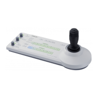
RM-B750
Section 1
Service Overview
1-1. Connector Input/Output Signals
MONITOR
*
(BNC Type)
SDTV (NTSC/PAL) : VBS output (1.0 V p-p, 75 Z)
HDTV : Y signal output (1.0 V p-p, 75 Z)
* : This signal is output all the time.
CAMERA
(8P, FEMALE)
No. Signal Specification
1 TX (+) RM SERIAL DATA
2 TX (_)
3 RX (+) CAMERA SERIAL DATA
4 RX (_)
5 VIDEO (GND) GND for VIDEO
6 POWER (+) IN RM POWER
7 POWER (_) IN GND for POWER
8 VIDEO (X) OUT VBS 1.0 V p-p, Zo = 75 Z
C CHASSIS GND CHASSIS GND
1-2. Connection Connector/Cable
Connection made with the connector panels during instal-
lation or service, should be made with the connectors/
complete cable assemblies specified in the following list,
or equivalent parts.
Connector function Connection connector/Cable
CAMERA 1-706-848-11 PLUG, 8P MALE or
(8P, FEMALE) 1-783-372-11 Connection cord
(10 m) (supplied)
MONITOR 1-569-370-12 PLUG, BNC
(BNC)
(External View)
1
7
6
4
8
5
2
3
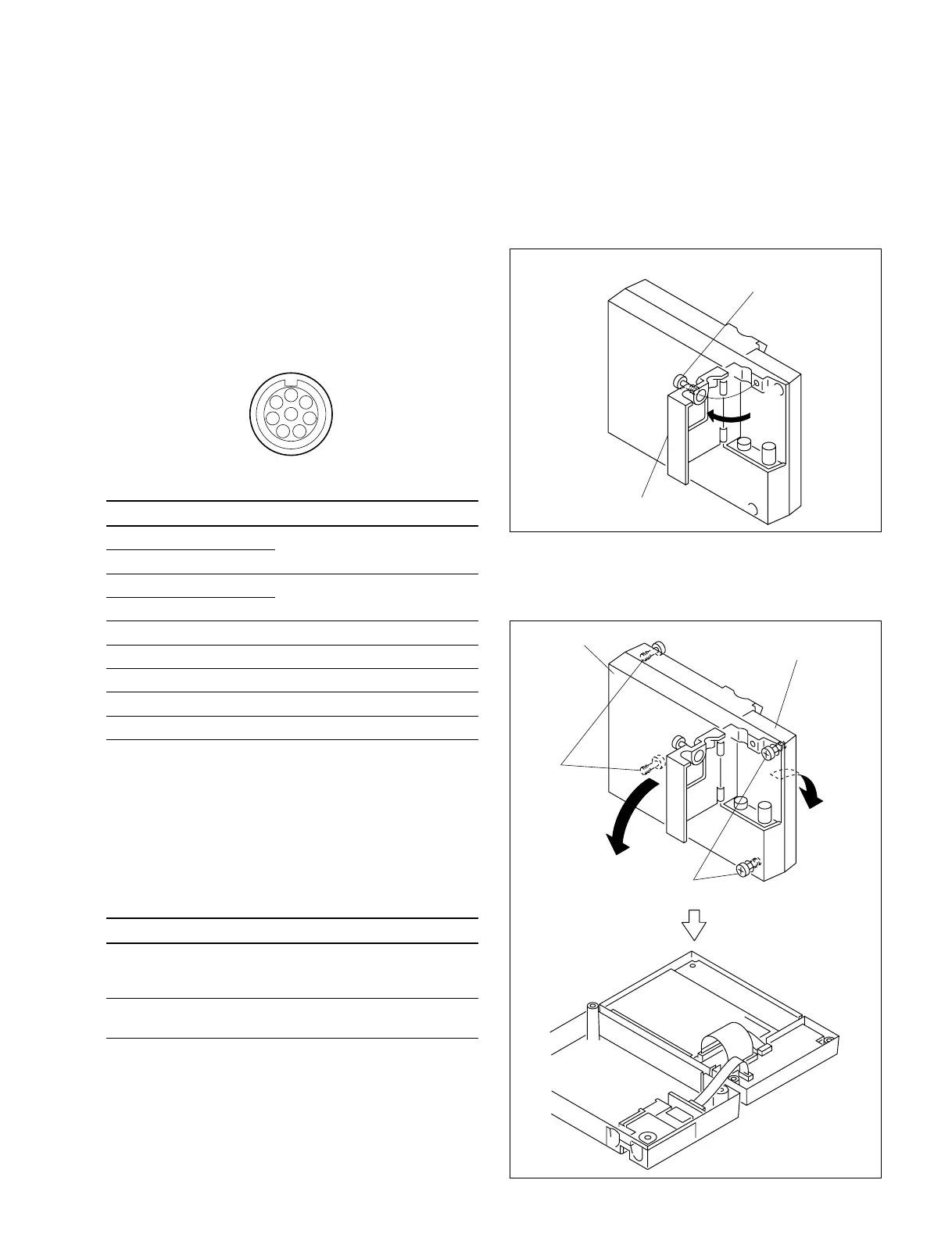
1-3. Opening the RM-B750
1. Loosen the screw (with drop-safe) and open the RM
connector cover in the direction of the arrow.
2. Loosen the four screws (with drop-safe) and open the
operation panel assembly and the bottom cover in the
direction of the arrow respectively.
RM connector cover
Screw
(with drop-safe)
Operation panel assembly
Bottom cover
Screws
(with drop-safe)
Screws
(with drop-safe)
 Loading...