Do you have a question about the Sony SLV-662HF and is the answer not in the manual?
Procedure for testing AC leakage from exposed metal parts to earth ground.
Identifies critical safety components and replacement guidelines.
Common issues and solutions for VCR operation.
Overall schematic layout showing interconnections between major boards.
Detailed schematics and wiring diagrams for various VCR sections.
Pin functions for IC160 related to mechanism control.
IC160 pin functions for servo and peripheral circuits.
IC160 pin functions for system control peripherals.
Detailed pin assignments and functions for the MA-341's microprocessor IC160.
Procedures for performing electrical alignments and adjustments.
Verifies power supply voltages and output levels.
Procedures for checking and adjusting servo system functions.
Standard and Hi-Fi audio adjustments for optimal performance.
Diagram showing locations of adjustment points on the MA-341 board.
Visual breakdown of VCR components for parts identification.
Comprehensive list of electrical components with part numbers and specifications.
| Brand | Sony |
|---|---|
| Model | SLV-662HF |
| Type | VCR |
| Video Format | VHS |
| Recording Speed | SP, LP, EP |
| Playback Speed | SP, LP, EP |
| Playback Head | 4-Head |
| Hi-Fi Stereo | Yes |
| Signal-to-Noise Ratio | 45 dB |
| Video Output | Composite |
| Tuner | Yes |
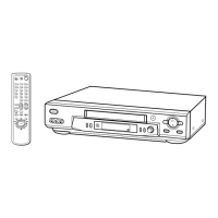
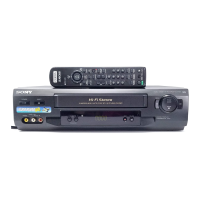
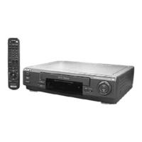
| Remote Control | Yes |
| Outputs | Composite video, Audio (RCA) |