EasyManua.ls Logo

Sony SLV-E510EE User Manual

Sony SLV-E510EE
64 pages
To Next Page IconTo Next Page
Page #1 background imageLoading...
Page #1 background image

Table of Contents

Question and Answer IconNeed help?

Do you have a question about the Sony SLV-E510EE and is the answer not in the manual?

Sony SLV-E510EE Specifications

General IconGeneral
TypeVCR
Video FormatVHS
Video StandardPAL
Hi-Fi StereoYes
Remote ControlYes
Playback FormatsVHS
Recording FormatsVHS
Recording SpeedSP, LP
Playback SpeedSP, LP
ConnectionsSCART
InputsAntenna
OutputsSCART
Power SupplyAC 220-240V, 50Hz

Summary

SAFETY CHECK-OUT

UPPER DRUM REPLACEMENT

Removal of Upper Drum

Step-by-step guide for safely removing the upper drum.

Mounting Upper Drum

Guide for correctly installing the upper drum assembly.

Getting Started

Unpacking

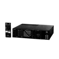
Checklist of items included with the VCR.

Setting up the remote commander

Instructions for inserting batteries and operating the remote.

Connecting the VCR

Additional connections

Enhancing picture and sound quality via EURO-AV and stereo connections.

Tuning your TV to the VCR

Setting up the VCR with EASY SET UP

Manual setup - Selecting a language

Manual setup - Presetting channels

Manually tuning and storing TV channels.

Disabling unwanted programme positions

If the picture is not clear

Manual setup - Selecting station names/setting up VIDEO Plus+

Setting up VIDEO Plus+ for satellite broadcasts

Manual setup - Changing/disabling programme positions

Reordering or disabling preset TV channels.

Manual setup - Setting the clock

Basic Operations

Playing a tape

How to insert, play, and manage video tapes.

Recording TV programmes

Recording TV programmes using VIDEO Plus+

To record satellite broadcasts

Setting the timer manually

Additional Operations

Playing/searching at various speeds

Navigating tapes at different playback speeds.

Recording TV programmes using the quick timer

Checking/changing/cancelling timer settings

Managing existing timer recording schedules.

Recording stereo and bilingual programmes

In NICAM system

Specifics of recording NICAM stereo and bilingual broadcasts.

Selecting the sound during playback

Searching using the index function

Adjusting the picture

Adjusting the tracking

Manual adjustment for picture stability and clarity.

About Optimum Picture Control (OPC)

Automatic picture quality enhancement system.

OPC playback

How OPC functions during tape playback.

OPC recording

How OPC functions during tape recording.

Editing

Connecting to a VCR or stereo system

Wiring instructions for recording and audio output.

Basic editing (when recording on this VCR)

Performing simple tape-to-tape editing.

Audio dubbing

Index to parts and controls

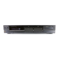
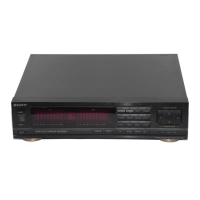
Reference guide to VCR components and buttons.

Front panel, with cover opened

Display window

Explanation of indicators shown in the VCR's display.

Rear panel

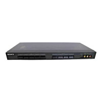
Identification of rear panel connectors and switches.

Remote commander

SECTION 2 DISASSEMBLY

FRONT PANEL ASSEMBLY, CASE AND MF-285 BOARD (E710)

Disassembly of the front panel assembly and case for E710 models.

FRONT PANEL ASSEMBLY AND CASE (E510, E810)

Disassembly of the front panel assembly and case for E510/E810 models.

CONTROL SWITCH BLOCK AND MF-285 BOARD (E510, E810)

DM-49 BOARD AND PS-357 BOARD

Disassembly instructions for DM-49 and PS-357 boards.

CASSETTE COMPARTMENT ASSEMBLY AND HI-25 BOARD

RP-199 BOARD

Disassembly steps for the RP-199 board.

MECHANISM CHASSIS ASSEMBLY

MA-253 BOARD

Disassembly of the MA-253 board.

INTERNAL VIEWS

CIRCUIT BOARDS LOCATION

FRONT PANEL AND CABINET ASSEMBLIES (E710)

FRONT PANEL AND CABINET ASSEMBLIES (E510, E810)

CHASSIS ASSEMBLY

MECHANISM CHASSIS ASSEMBLY (1)

MECHANISM CHASSIS ASSEMBLY (2)

MECHANISM CHASSIS ASSEMBLY (4)

MECHANISM CHASSIS ASSEMBLY (3)

SYSTEM CONTROL – VIDEO BLOCK INTERFACE (MA-253 BOARD IC201)

SYSTEM CONTROL – SERVO PERIPHERAL CIRCUIT INTERFACE (MA-253 BOARD IC201)

SYSTEM CONTROL – MECHANISM INTERFACE (MA-253 BOARD IC201)

SYSTEM CONTROL – SYSTEM CONTROL PERIPHERAL CIRCUIT INTERFACE (MA-253 BOARD IC201)

SYSTEM CONTROL – NORMAL AUDIO BLOCK INTERFACE (MA-253 BOARD IC201) (SLV-E510)

Pin function details for normal audio block interface.

SYSTEM CONTROL – RF MODULATOR, INPUT SELECTION BLOCK INTERFACE (MA-253 BOARD IC201)

SERVO/SYSTEM CONTROL MICROPROCESSOR PIN FUNCTION (MA-253 BOARD IC201 CXP-87630-009Q)

TUNER/TIMER MODE CONTROL PIN FUNCTION (MA-253 BOARD IC151)

SECTION 7 ADJUSTMENTS

7-1. MECHANICAL ADJUSTMENTS

Details on mechanical adjustments for the VCR.

7-2. ELECTRICAL ADJUSTMENTS

Includes pre-adjustment preparations, instruments, connections, setup, and alignment tape.

Related product manuals