EasyManua.ls Logo

Sony SLV-E850B User Manual

Sony SLV-E850B
18 pages
To Next Page IconTo Next Page
Page #1 background imageLoading...
Page #1 background image
SLV-E850B/E850UX/E880EG/F900B/F900NP/F900UX/
F900VC/F990B/F990NP/F990UX/F990VC
RMT-V222C/V222D/V222E/V223C/V240/V240A/V240B/V240C/V240D
French Model
SLV-E850B/F900B/F990B
UK Model
SLV-E850UX/F900UX/F990UX
Greek Model
SLV-E880EG
Spanish Model
SLV-F900NP/F990NP
Germany Model
SLV-F900VC/F990VC
SERVICE MANUAL
VIDEO CASSETTE RECORDER
MICROFILM
S MECHANISM
Refer to the SERVICE MANUAL of VHS MECHANICAL
ADJUSTMENTS
for MECHANICAL ADJUSTMENTS.
(9-921-647-11)
G
j
SPECIFICATIONS
Photo : SLV-F990
Question and Answer IconNeed help?

Do you have a question about the Sony SLV-E850B and is the answer not in the manual?

Sony SLV-E850B Specifications

General IconGeneral
TypeVCR
Video FormatVHS
Audio OutputMono
Number of Heads2
Remote ControlYes
TunerYes
TimerYes
Playback SpeedSP, LP
Dimensions360 x 95 x 230 mm
Recording SystemRotary 2-head helical scan system

Summary

Unit Specifications Overview

System Specifications

Details channel coverage, RF output signal, and aerial connection specifications.

Input and Output Specifications

Lists and describes various input and output connectors and their signal assignments.

General Unit Specifications

Covers power requirements, consumption, operating temperature, dimensions, and mass.

Included Accessories

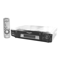
Lists the items included with the video cassette recorder.

RP-231 REC/PB AMP Schematic Diagram

MA-316 Video and Normal Audio Schematic Diagram

MA-316 Servo and System Control Schematic Diagram

MA-316 On Screen Display Schematic Diagram

MA-316 AFM Audio Schematic Diagram

MA-316 Tuner Schematic Diagram

MA-316 Follow TV, PDC, VPS Schematic Diagram

MA-316 I/O Schematic Diagram

FR-128 Mode Control Schematic Diagram

SE-69 Secam Video Signal Process Schematic Diagram

DM-73 Operation Switches Schematic Diagram

NR-26 DNR Processor Schematic Diagram

ML-15 Serial Transfer Schematic Diagram

AT-23 Board Schematic Diagram (F900/F990)

AT-24 Board Schematic Diagram (F900/F990)

Switch Block Schematic Diagram

SW-300 Remote Control Receiver Schematic Diagram

Power Block SR826 Switching Regulator Schematic Diagram

Related product manuals