Do you have a question about the Sony SLV-EZ715 and is the answer not in the manual?
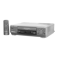
Instructions for inserting batteries and using the remote commander.
Guide on connecting the VCR to TV for viewing and audio/video output.
Steps for tuning the TV to receive VCR signals.
How to preset receivable channels automatically using One Touch Tuning or AUTO PRESET.
Procedure for manually setting channel numbers and disabling unwanted positions.
Guide to setting up G-CODE for timer recordings.
Instructions for changing or disabling programme positions on the VCR.
Steps to set the VCR's internal clock for timer recording features.
How to insert a tape and play back recorded content.
Covers tasks like setting colour system and other playback controls.
Steps for recording TV programs using standard functions and REC SPEED.
Guide to setting timer recordings using the Easy Timer function.
Instructions for recording using G-CODE numbers, including satellite broadcasts.
Explains how to search for recordings using Easy Timer, time, blank sections, or index marks.
Controls for playback speed, picture quality, and stereo/bilingual audio.
How to check, change, or cancel timer settings, including overlap handling.
Explains how to change various system menu options.
Guides on connecting VCR to TV, stereo systems, and other VCRs.
Information on the built-in tape cleaner and head condition sensor.
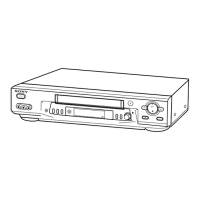
Steps for removing the outer case, front panel, and internal boards.
Disassembly of the mechanism deck and identification of internal components.
Diagram showing the placement of various circuit boards within the VCR.
High-level overview of the VCR's system architecture.
Block diagrams for video, servo, audio, tuner, mode, and power systems.
Basic frame schematic and detailed MA-402 board schematics/PWBs.
Schematics and PWB layouts for GK-12, NK-11, FJ-31, DM-98, and DI-81 boards.
Pin functions for video, servo, mechanism, and audio blocks of IC101.
Pin function descriptions for NICAM and ZWEITON processor ICs.
List of error codes displayed by the VCR and their meanings.
Table of mode codes indicating operation status during an error.
Lists required instruments, connections, and setup for electrical adjustments.
Procedures for power, servo, audio, and tuner system adjustments and checks.
Exploded views and parts lists for front panel, chassis, and mechanism deck sections.
Comprehensive list of electrical components for MA-402, NK-11, GK-12, etc.
| Brand | Sony |
|---|---|
| Model | SLV-EZ715 |
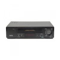
| Type | VCR |
| Video Format | VHS |
| Recording Speed | SP, LP, EP |
| Playback Speed | SP, LP, EP |
| Playback Head | 4 |
| Number of Heads | 4 |
| Timer Recording | Yes |
| Remote Control | Yes |
| Inputs | RF |
| Outputs | RF |
| Tuner | Built-in |