Do you have a question about the Sony SLV-EX80S and is the answer not in the manual?
VCR system formats, heads, tape speed, recording time, and general specifications.
Details on audio/video connectors and timer functions.
Instructions for removing the front panel, rear panel, and circuit boards like DM-98, DI-81, FJ-31, and MA-402.
Guidance on disassembling the mechanism deck and identifying internal components.
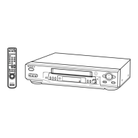
Instructions for inserting batteries and using the remote control.
Guide to connecting the VCR to TVs and stereo systems for optimal performance.
Adjusting the RF unit switch and selecting the on-screen display language.
Procedures for automatically or manually tuning and saving TV channels.
Steps to set the VCR's internal time and date for proper timer operation.
Guides on tape playback, basic recording, and NTSC tape playback.
Step-by-step guide to manually program recording timers for multiple programs.
Methods for locating specific points, blank sections, or indexed programs on a tape.
How to search by time and play/search tapes at various speeds.
Instructions for recording programs synchronized with other equipment's timers.
Checking, changing, or canceling programmed timer recording settings.
How to record stereo and bilingual audio programs and select sound during playback.
Adjusting tracking, R2 function, and APC for optimal picture clarity.
Navigating system menus and understanding sound recording tracks.
Guides for connecting to another VCR for editing and connecting to a stereo system.
Instructions for attaching external antenna connectors and UHF/VHF band mixers.
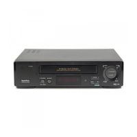
Identifies controls on the front panel and indicators in the display window.
Shows components on the rear panel and the layout of the remote commander buttons.
Presents the overall block diagram and specific diagrams for key VCR systems.
Provides the main frame schematic and detailed diagrams for the MA-402 board's various blocks.
Covers interfaces for Video, Servo, Mechanism, and Audio blocks connected to the system control IC.
Details the pin functions for the OSD microprocessor within the system control IC.
Covers pre-adjustment prep, instruments, connections, setup, alignment tapes, I/O specs, power supply, servo, audio, and tuner system adjustments.
Diagram illustrating component locations on the MA-402 board for adjustments.
Illustrates and lists parts for the front panel, upper case, chassis, and mechanism deck assemblies.
Comprehensive list of electrical components including resistors, capacitors, transistors, ICs, connectors, and switches.
| Brand | Sony |
|---|---|
| Model | SLV-EX80S |
| Type | VCR |
| Video Format | VHS |
| Recording Speed | SP, LP, EP |
| Playback Speed | SP, LP, EP |
| Number of heads | 4 |
| Hi-Fi Stereo | Yes |
| Tuner | Yes |
| Remote Control | Yes |
| Inputs | Composite |
| Outputs | Composite |