EasyManua.ls Logo

Sony SLV-ED1PL User Manual

Sony SLV-ED1PL
135 pages
To Next Page IconTo Next Page
Page #1 background imageLoading...
Page #1 background image
MICROFILM
SERVICE MANUAL
Korean Model
SLV-ED7KR
Philippine Model
SLV-ED1PL/ED4PL/ED8PL
RMT-V247B/V248
VIDEO CASSETTE RECORDER
SLV-ED1PL/ED4PL/ED7KR/ED8PL
G
Refer to the SERVICE MANUAL of VHS MECHANICAL
ADJUSTMENTS VI for MECHANICAL ADJUSTMENTS.
(9-921-647-11)
* The abbreviations of ED1, ED4, ED7 and ED8 contained in this service manual
are indicated when these models are common to all their corresponding mod-
els as given below.
Photo: SLV-ED1PL
S MECHANISM
ED1PL
ED1
Abbreviated
model name
All model
names
SLV-
ED4PL
ED4
ED7KR
ED7
ED8PL
ED8
SPECIFICATIONS
– Continued on next page –
Inputs and outputs
LINE-1 IN
VIDEO IN, phono jack (1)
Input signal: 1 Vp-p, 75 ohms, unbalanced,
sync negative
AUDIO IN, phono jack (1) (ED1/ED4)
AUDIO IN, phono jack (2) (ED7/ED8)
Input level: 327 mVrms
Input impedance: more than 47 kilohms
LINE-2 IN (ED7/ED8)
VIDEO IN, phono jack (1)
Input signal: 1 Vp-p, 75 ohms, unbalanced,
sync negative
AUDIO IN, phono jack (2)
Input level: 327mVrms
Input impedane: more than 47 kilohms
LINE OUT
VIDEO OUT, phono jack (1)
Output signal: 1 Vp-p, 75 ohms, unbal-
anced, sync negative
AUDIO OUT, phono jack (1) (ED1/ED4)
AUDIO OUT, phono jack (2) (ED7/ED8)
Standard output: 327 mVrms
Load impedance; 47 kilohms
Output impedance: less than 10 kilohms
Timer section
Clock
Quartz locked
Timer indication
12-hour cycle
Timer setting
8 programs per month (max.)
Power back-up
Built-in self-charging capacitor
Back-up duration: up to 1 hour at a time
General
Power requirements
110 – 240 V AC, 50/60 Hz
Power consumption
19W (ED1/ED4)
22W (ED7/ED8)
Operating temperature
5 ˚C to 40 ˚C
Storage temperature
–20 ˚C to 60 ˚C
System
Format
VHS NTSC standard
Video recording system
Rotary head helical scanning FM system
Video heads
Double azimuth two heads
Video signal
NTSC color, EIA standards
Tape speed
SP: 33.35 mm/s
EP: 11.11 mm/s
LP: 16.67 mm/s, playback only
Maximum recording
playback time
8 hrs. in EP mode (with T-160 tape)
Fast-forward and rewind time
Approx. 3 min. (with T-120 tape)
Tuner section
Channel coverage
VHF 2 to 13
UHF 14 to 69
CATV A-8 to A-1, A to W, W+1 to W+84
Antenna
75-ohm antenna terminal for VHF/UHF
Ver 1.0 1998. 08

Table of Contents

Question and Answer IconNeed help?

Do you have a question about the Sony SLV-ED1PL and is the answer not in the manual?

Sony SLV-ED1PL Specifications

General IconGeneral
Remote ControlYes
SoundMono
TunerYes
Power Consumption18W
TypeVCR
Recording SpeedSP, LP
Playback SpeedSP, LP
ConnectionsAntenna
Recording FormatsPAL
InputsAntenna
OutputsComposite video

Summary

Specifications

Inputs and outputs

Details video and audio input/output specifications, impedance, and levels.

Feature Difference

SAFETY CHECK-OUT

Procedures for safety checks after repair before releasing the unit to the customer.

1. DISASSEMBLY

SECTION 1 GENERAL

SECTION 2 DISASSEMBLY

2-9. CIRCUIT BOARDS LOCATION

SECTION 3 BLOCK DIAGRAMS

Introduction to the block diagrams of the VCR.

3-1. OVERALL BLOCK DIAGRAM

3-2. VIDEO1 BLOCK DIAGRAM

Block diagram of the Video 1 signal path.

3-3. VIDEO2 BLOCK DIAGRAM

3-4. SERVO/SYSTEM CONTROL BLOCK DIAGRAM

Block diagram for servo and system control.

3-5. AUDIO BLOCK DIAGRAM

3-6. TUNER BLOCK DIAGRAM

Block diagram of the tuner section.

3-7. MODE CONTROL BLOCK DIAGRAM

3-8. POWER BLOCK DIAGRAM

Block diagram of the power supply section.

SECTION 4 PRINTED WIRING BOARDS AND SCHEMATIC DIAGRAMS

4-1. FRAME SCHEMATIC DIAGRAM

Overall frame schematic diagram.

4-2. PRINTED WIRING BOARD AND SCHEMATIC DIAGRAMS

MA-323 (HEAD AMP) SCHEMATIC DIAGRAM

Schematic for the MA-323 Head Amplifier.

MA-323 (VIDEO, AUDIO) SCHEMATIC DIAGRAM

MA-323 (SYSTEM CONTROL) SCHEMATIC DIAGRAM

MA-323 (SERVO CONTROL) SCHEMATIC DIAGRAM

Schematic diagram for the servo control system.

MA-323 (Hi-Fi AUDIO) SCHEMATIC DIAGRAM

MA-323 (IO) SCHEMATIC DIAGRAM

Schematic diagram for the Input/Output section.

MA-323 (TUNER) SCHEMATIC DIAGRAM

MA-323 (MODE CONTROL) SCHEMATIC DIAGRAM

Schematic diagram for the mode control circuitry.

MA-323 (FL DRIVER) SCHEMATIC DIAGRAM

MA-323 (POWER SUPPLY) SCHEMATIC DIAGRAM

Schematic diagram for the power supply unit.

DS-80 (MODE CONTROL) PRINTED WIRING BOARD AND SCHEMATIC DIAGRAM

DM-76 BOARD, MF-312 BOARD

SR-708 (POWER SUPPLY) PRINTED WIRING BOARD

SECTION 5 INTERFACE, IC PIN FUNCTION DESCRIPTION

Details on IC pin functions and interfaces between system blocks.

5-1. SYSTEM CONTROL – VIDEO BLOCK INTERFACE (MA-323 BOARD IC161)

5-2. SYSTEM CONTROL – SERVO PERIPHERAL CIRCUIT INTERFACE (MA-323 BOARD IC161)

Interface signals between system control and servo circuits.

5-3. SYSTEM CONTROL – MECHANISM BLOCK INTERFACE (MA-323 BOARD IC161)

5-4. SYSTEM CONTROL – AUDIO BLOCK INTERFACE (MA-323 BOARD IC161)

Interface signals for audio processing and control.

5-5. SERVO/SYSTEM/TIMER/TUNER CONTROL MICROPROCESSOR PIN FUNCTION (MA-323 BOARD IC161)

5-6. KOREAN STEREO PROCESSOR PIN FUNCTION (NK-11 BOARD IC1)

Pin function description for the Korean stereo processor IC.

SECTION 6 ERROR CODES

SECTION 7 ADJUSTMENTS

7-1. MECHANICAL ADJUSTMENTS

Procedures for mechanical adjustments on the VCR.

7-2. ELECTRICAL ADJUSTMENTS

Detailed steps for electrical adjustments of various VCR circuits.

2-2. POWER SUPPLY ADJUSTMENT

2-4. AUDIO SYSTEM ADJUSTMENTS

2-4-2. Normal Audio System Adjustment

2-5. TUNER SYSTEM ADJUSTMENT

SECTION 8 REPAIR PARTS LIST

8-1. EXPLODED VIEWS

Exploded diagrams showing the assembly of VCR components.

8-1-1. FRONT PANEL AND CABINET ASSEMBLIES (ED1)

8-1-3. FRONT PANEL AND CABINET ASSEMBLIES (ED4/ED7/ED8)

8-1-5. MECHANISM CHASSIS ASSEMBLY (1)

8-1-7. MECHANISM CHASSIS ASSEMBLY (3)

8-2. ELECTRICAL PARTS LIST

List of electrical components including part numbers and descriptions.

1. PREPARATION FOR MECHANISM CHECKS, ADJUSTMENTS AND REPLACEMENT

1-1-1. LOADING AND THREADING PROCEDURE WITH HANDS

1-2-1. UNLOADING AND UNTHREADING PROCEDURE WITH HANDS

2. PERIODIC CHECK AND REPLACEMENT

3. MAINLY MECHANICAL PARTS REPLACEMENT

3-2. DRUM ASSEMBLY

3-4. RUBBER BELT, CAPSTAN MOTOR

3-6. FEH ASSEMBLY

3-8. RVS BRAKE ARM ASSEMBLY

3-12. FL SLIDER BLOCK ASSEMBLY

3-14. CAPSTAN BRAKE ASSEMBLY, CAPSTAN BRAKE SHAFT

3-18. LOADING (T) AND LOADING (S) GEAR ASSEMBLIES

3-23. DRUM BASE, HC ROLLER BLOCK ASSEMBLY

3-25. TG1 ASSEMBLY, REEL (S) TABLE

3-27. LUMINOUS PLATE

4. ADJUSTMENT

Section dedicated to various adjustment procedures for the VCR.

4-1. TAPE PATH ADJUSTMENT

4-1-2. CHECKING THE TENSION AND TORQUE

4-1-4. HEIGHT ADJUSTMENT OF GUIDE ROLLERS NO. 3 AND NO. 5

4-1-6. X-VALUE FINE ADJUSTMENT

4-1-8. CHECKING THE LINEARITY AND FLUCTUATION OF THE RF OUTPUT

5. EXPLODED VIEWS

Exploded diagrams of the VCR mechanism components.
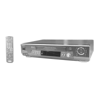
5-1. MECHANISM DECK-1

5-3. MECHANISM DECK-3

Related product manuals