EasyManua.ls Logo

Sony SLV-ED40PS User Manual

Sony SLV-ED40PS
140 pages
To Next Page IconTo Next Page
Page #1 background imageLoading...
Page #1 background image
MICROFILM
SERVICE MANUAL
Australian Model
SLV-EZ10AZ/EZ40AZ/EZ60AZ/EZ70AS
E Model
SLV-ED10MPS/ED10PS/ED40PS/ED60PS/ED70MN
ME Model
SLV-ED10ME/ED10SG/ED40ME/
ED40SG/ED60ME/ED60SG
Newzealand Model
SLV-EZ10AZ/EZ40AZ/EZ60AZ/EZ70NZ
VIDEO CASSETTE RECORDER
G
Refer to the SERVICE MANUAL of VHS MECHANICAL
ADJUSTMENTS VI for MECHANICAL ADJUSTMENTS.
(9-921-647-11)
* The abbreviations of ED10, ED40, ED60, ED70, EZ10, EZ40, EZ60 and EZ70
contained in this service manual are indicated when these models are com-
mon to all their corresponding models as given below.
S MECHANISM
ED10ME
ED10MPS
ED10PS
ED10SG
ED10
Abbreviated
model name
All model
names
SLV-
ED40 ED60
ED70MN
ED70
EZ10AZ
EZ10
EZ40AZ
EZ40
ED60AZ
EZ60 EZ70
EZ70AS
EZ70NZ
ED40ME
ED40PS
ED40SG
ED60ME
ED60PS
ED60SG
RMT-V245/V245A/V245C/V247/V247C/V247D/V248C
SLV-ED10ME/ED10MPS/ED10PS/ED10SG/ED40ME/ED40PS/ED40SG/ED60ME/
ED60PS/ED60SG/ED70MN/EZ10AZ/EZ40AZ/EZ60AZ/EZ70AS/EZ70NZ
Photo: SLV-ED70MN
w
w
w
.
x
i
a
o
y
u
1
6
3
.
c
o
m
Q
Q
3
7
6
3
1
5
1
5
0
9
9
2
8
9
4
2
9
8
T
E
L
1
3
9
4
2
2
9
6
5
1
3
9
9
2
8
9
4
2
9
8
0
5
1
5
1
3
6
7
3
Q
Q
TEL 13942296513 QQ 376315150 892498299
http://www.xiaoyu163.com

Table of Contents

Question and Answer IconNeed help?

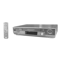
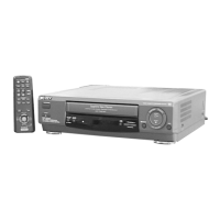
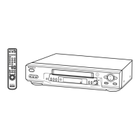
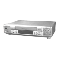
Do you have a question about the Sony SLV-ED40PS and is the answer not in the manual?

Sony SLV-ED40PS Specifications

General IconGeneral
TypeVCR
Number of Heads4
Audio SystemMono
Remote ControlYes
Dimensions360 x 250 x 90 mm
Recording SpeedSP, LP
Playback SpeedsSP, LP
OutputsComposite video
ConnectionsComposite Video, Audio (RCA)
InputsComposite Video, Audio (RCA)

Summary

SERVICE MANUAL

SPECIFICATIONS

Inputs and outputs

Lists all input and output connections and their specifications.

SERVICE NOTE

1. DISASSEMBLY

Provides a step-by-step guide for disassembling the unit.

SECTION 1 GENERAL

Step 3 Connecting the VCR

Instructions for connecting the VCR to a TV and other devices.

Step 4 Tuning your TV to the VCR

Steps to tune the TV to receive signals from the VCR.

Step 6 Presetting channels

Instructions for automatically and manually preset TV channels.

Step 6 Presetting channels (continued)

Instructions for automatically and manually preset TV channels.

Basic Operations

Covers fundamental operations like playing a tape.

Basic Operations (continued)

Covers fundamental operations like playing a tape.

Recording programmes TV

Instructions on how to record TV programs.

Recording programmes TV (continued)

Instructions on how to record TV programs.

Recording programmes using the easy timer

Guide to using the easy timer for recording.

Setting the timer manually

Instructions for manually setting recording timers.

Recording programmes using the quick timer

Instructions for using the quick timer feature.

Adjusting the picture

Guide to adjusting picture settings.

SECTION 2 DISASSEMBLY

2-1. UPPER CASE REMOVAL

Step-by-step guide to remove the upper case.

2-3. REAR PANEL REMOVAL

Step-by-step guide to remove the rear panel.

2-2. GK-12, NK-11, RJ-82 BOARD REMOVAL

Instructions for removing specific circuit boards.

2-4. FRONT PANEL SECTION REMOVAL

Step-by-step guide to remove the front panel section.

2-5. POWER BLOCK REMOVAL

Instructions for removing the power block.

2-7. MA-350 BOARD REMOVAL

Instructions for removing the MA-350 board.

2-6. MECHASISM DECK REMOVAL

Instructions for removing the mechanism deck.

SECTION 3 BLOCK DIAGRAMS

3-1. OVERALL BLOCK DIAGRAM

A comprehensive block diagram of the entire system.

SECTION 4 PRINTED WIRING BOARDS AND SCHEMATIC DIAGRAMS

SECTION 5 INTERFACE, IC PIN FUNCTION DESCRIPTION

5-1. SYSTEM CONTROL – VIDEO BLOCK INTERFACE (MA-350 BOARD IC161)

Pin functions for video interface on MA-350 board IC161.

5-2. SYSTEM CONTROL – SERVO PERIPHERAL CIRCUIT INTERFACE (MA-350 BOARD IC161)

Pin functions for servo interface on MA-350 board IC161.

5-3. SYSTEM CONTROL – MECHANISM BLOCK INTERFACE (MA-350 BOARD IC161)

Pin functions for mechanism interface on MA-350 board IC161.

5-4. SYSTEM CONTROL – AUDIO BLOCK INTERFACE (MA-350 BOARD IC161)

Pin functions for audio interface on MA-350 board IC161.

5-6. NICAM PROCESSOR PIN FUNCTION (NK-11 BOARD IC1)

Pin functions for the NICAM processor on NK-11 board IC1.

5-7. ZWEITON PROCESSOR PIN FUNCTION (GK-12 BOARD IC001)

Pin functions for the ZWEITON processor on GK-12 board IC001.

SECTION 6 ERROR CODES

SECTION 7 ADJUSTMENTS

7-2. ELECTRICAL ADJUSTMENTS

Procedures for electrical adjustments and calibration.

2-3. SERVO SYSTEM ADJUSTMENT

Details servo system adjustments, including RF switching position.

2-2. POWER SUPPLY ADJUSTMENTS

Procedures for checking and adjusting power supply voltages.

2-4. AUDIO SYSTEM ADJUSTMENTS

Instructions for adjusting the audio system, including Hi-Fi audio.

2-4-1. Hi-Fi Audio System Adjustment

Specific steps for adjusting the Hi-Fi audio system.

2-4-2. Normal Audio System Adjustment

Steps for adjusting the normal audio system.

3. Overall Level Characteristic and Distortion Factor Check

Checks for record/play levels and distortion.

4. Overall S/N Check

Checks the signal-to-noise ratio.

2-5. TUNER SYSTEM ADJUSTMENT

Adjustments for the tuner system.

2-5-1. Separation Adjustment

Adjusts separation of audio channels.

1. PREPARATION FOR MECHANISM CHECKS, ADJUSTMENTS AND REPLACEMENT

2. PERIODIC CHECK AND REPLACEMENT

2-6. HOW TO USE THE MODE SELECTOR II FOR ADJUSTING S TYPE MECHANISM ASSEMBLY

Guide on using the mode selector for S type mechanism adjustments.

2-7. PHASE ADJUSTMENT ON ATTACHING S TYPE MECHANISM ASSEMBLY

Procedure for phase adjustment of the S type mechanism.

3. MAINLY MECHANICAL PARTS REPLACEMENT

4. ADJUSTMENT

4-1. TAPE PATH ADJUSTMENT

Procedures for adjusting the tape path.

4-1-1. TENSION REGULATOR (TG1) POSITION/ TENSION ADJUSTMENT

Adjusting tension regulator position and tension.

2. Checking false tracking

Procedures for checking false tracking.

Reference

X-VALUE ADJUSTMENT (Using the tape having no version No.)

X-value adjustment procedure using a specific tape.

4-1-5. ACE HEAD ASSEMBLY HEIGHT AND AZIMUTH ADJUSTMENT

Adjusting ACE head assembly height and azimuth.

4-1-6. X-VALUE FINE ADJUSTMENT

Fine adjustment of X-value.

4-1-7. HEIGHT ADJUSTMENT OF GUIDE ROLLER NO. 8

Adjusting height of guide roller No. 8.

4-1-8. CHECKING THE LINEARITY AND FLUCTUATION OF THE RF OUTPUT

Checking RF output linearity and fluctuation.

Related product manuals