Do you have a question about the Sony SLV-ED818 and is the answer not in the manual?
Lists different regional models and key features like Hi-Fi and G-CODE.
Details color systems, TV systems, channel coverage, inputs, and outputs.
Covers power requirements, consumption, operating/storage temperatures, dimensions, and mass.
Outlines safety checks after service and highlights critical components, emphasizing SONY part usage.
Table detailing differences in HEAD/CH, NTSC, ME-SECAM, RCA inputs/outputs, and Modulator System.
Provides a visual flowchart of the disassembly sequence for major components and sub-assemblies.
Instructions on inserting batteries and using the remote commander for VCR operation.
Guides on connecting the VCR to a TV via aerial and mains power for viewing.
Steps to tune the television to receive the VCR's signal.
Details on automatically presetting receivable channels using One Touch Tuning.
Tips for improving picture clarity if initial tuning is not optimal.
Step-by-step guide for manually setting channels and programme positions.
Instructions on disabling or removing unwanted programme positions.
How to use fine tuning to improve picture clarity when AFT is insufficient.
Tables showing channel number correspondence for B/G system across various regions.
Tables mapping channel numbers for D/K, M, and U.S.A. systems across regions.
Guide to setting up the G-CODE system for timer recordings, including satellite broadcasts.
How to change or disable programme positions after initial setup.
Instructions on how to disable specific programme positions.
Step-by-step guide to set the VCR's internal clock for accurate timer functions.
Instructions for inserting, playing, and using the time counter for tape playback.
How to adjust the VCR's color system setting based on the recorded tape's format.
Steps for recording TV programs, including selecting programme position and tape speed.
Guide to setting up timer recordings using the Easy Timer function.
Detailed steps for manually setting timer recordings, including date, time, and programme position.
How to set or change the VCR's clock using the Easy Clock function.
Instructions for recording TV programs using G-CODE numbers from programme guides.
How to record satellite programs using the G-CODE system when available.
How to find the beginning of a program recorded with the Easy Timer function.
Locating the current tape position and viewing remaining tape time.
Finding an empty section on the tape for recording.
Using index signals to locate specific recorded sections on a tape.
Locating specific points on a tape by elapsed time.
Controlling playback and search speeds, including slow motion and frame-by-frame.
How to set the VCR to stop recording automatically after a specified time.
Checking, changing, or cancelling programmed timer settings.
How to select audio tracks for stereo and bilingual broadcasts in ZWEITON and NICAM systems.
Adjusting tracking, R² function, and Adaptive Picture Control (APC) for optimal picture quality.
Explains how to change various menu options like AUDIO MIX, HIFI AUDIO, APC, and TAPE LENGTH.
Guides on connecting the VCR to other VCRs or stereo systems for recording and playback.
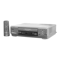
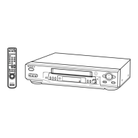
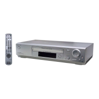
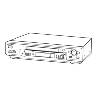
Identifies and locates controls on the VCR's front panel and the remote commander.
Identifies rear panel connectors and key indicators on the VCR's display window.
Steps for disassembling the case, front panel, and related blocks.
Instructions for removing DM-98, DI-81, and FJ-31 interface boards.
Steps for detaching the rear panel of the VCR.
Guide for removing the MA-402 main board assembly.
Detailed steps for removing and disassembling the VCR's mechanism deck.
Views identifying key internal components such as drum assemblies, motors, and sensors.
Diagram showing the physical placement of main circuit boards within the VCR.
A comprehensive overview of the VCR's main functional blocks and their interconnections.
Details the video signal path, including processing ICs and inputs/outputs.
Illustrates the servo control system, motor drivers, and system control interfaces.
Depicts the audio signal path, including Hi-Fi processing, input/output stages, and volume control.
Shows the tuner block, including RF input, IF processing, and audio/video output signals.
Illustrates the mode control logic, including inputs from front panel and interface boards.
Details the power supply circuit, AC input, rectification, and voltage regulation stages.
Explains symbols, notations, and conventions used in the PWB layouts and schematic diagrams.
Shows the overall schematic layout connecting major modules like FE-127, MA-402, and interface boards.
Printed wiring board layout for the MA-402 main board, showing component placement.
Identifies component locations on the MA-402 board by reference number.
Shows the placement of GK-12, NK-11, FJ-31, DM-98, and DI-81 boards.
Schematic diagram detailing the video and audio signal processing circuits on the MA-402 board.
Illustrates typical waveforms at various ICs within the video and audio blocks for troubleshooting.
Schematic diagram for the system control section of the MA-402 board, showing IC functions.
Shows typical waveforms for IC101 in the system control block, aiding in diagnosis.
Schematic diagram for the servo control section of the MA-402 board, detailing motor control and sensor signals.
Schematic diagram for the Hi-Fi audio processing section of the MA-402 board.
Schematic diagram of the tuner section on the MA-402 board, showing RF and IF signal paths.
Schematic diagram illustrating the input and output connections and signal paths on the MA-402 board.
Schematic diagram for the mode control logic, including interface with DI-81 and DM-98 boards.
Schematic diagram of the power supply section on the MA-402 board, showing voltage regulation and distribution.
Printed wiring board layout and schematic diagram for the GK-12 ZWEITON interface board.
Printed wiring board layout and schematic diagram for the NK-11 NICAM interface board.
Printed wiring board layouts and schematic diagrams for FJ-31 (Line 2 In) and DM-98 (Function) boards.
Printed wiring board layout and schematic diagram for the DI-81 Dial Timer board.
Details pin functions for IC101 in the video block, including signal I/O and operating modes.
Describes pin functions for IC101 related to the servo peripheral circuits, covering motor and sensor signals.
Explains pin functions for IC101 in the mechanism block, detailing cassette handling and motor control signals.
Details pin functions for IC101 in the audio block, covering mute, AF signals, and erase functions.
Comprehensive pin function list for IC101 covering servo, system control, OSD, tuner, and interface signals.
Pinout details for the NICAM processor IC on the NK-11 board, covering audio and control signals.
Pinout details for the ZWEITON processor IC on the GK-12 board, covering audio and control signals.
Lists VCR error codes and their corresponding descriptions, indicating operational faults.
Lists mode codes displayed during errors, corresponding to specific VCR operations or states.
Refers to a separate manual for mechanical adjustments, indicating it's not detailed here.
Lists necessary instruments, connection methods, and setup procedures for electrical adjustments.
Details procedures for checking various DC voltage outputs from the power supply circuit.
Method for adjusting the RF switching position to improve tape interchangeability.
Steps for adjusting Hi-Fi audio, including AF switching, frequency response, and S/N checks.
Procedures for adjusting normal audio system functions like ACE head and E-E output level.
Checks for overall level, distortion factor, and frequency response in audio systems.
Methods for checking Signal-to-Noise (S/N) ratio and performing normal audio system adjustments.
Covers tuner system adjustments, including separation adjustment for Lch/Rch.
Diagrams showing the physical locations of components relevant to adjustments on MA-402 and GK-12 boards.
Exploded view illustrating parts for the front panel and upper case assembly, with part numbers.
Exploded view showing parts related to the chassis and main boards like MA-402.
Exploded view detailing components of the mechanism deck, including gears, motors, and sensors.
Continues the exploded view of the mechanism deck, listing more parts like rollers and brakes.
Final part of the mechanism deck exploded view, covering sliders, levers, and springs.
Lists electrical components for DI-81, DM-98, and FJ-31 boards, including switches, diodes, and resistors.
Lists electrical components for FJ-31 and GK-12 boards, including resistors, capacitors, and connectors.
Lists capacitors C016 through C304 for the MA-402 board, with specifications.
Lists capacitors C232 through C375 for the MA-402 board, with specifications.
Lists capacitors C378 through C457 for the MA-402 board, with specifications.
Lists diodes, connectors, ICs, and jumper resistors for the MA-402 board.
Lists inductors, filters, and fluorescent tube indicators for the MA-402 board.
Lists resistors R001 through R380 for the MA-402 board, with specifications.
Lists resistors R383 through R428 for the MA-402 board, with specifications.
Lists resistors R451 through R914 for the MA-402 board, with specifications.
Lists transformers, crystals, connectors, and resistors for MA-402 and NK-11 boards.
Lists diodes, ICs, hardware components like screws, and other parts for the MA-402 board.