EasyManua.ls Logo

Sony SLV-ED60PS User Manual

Sony SLV-ED60PS
140 pages
To Next Page IconTo Next Page
Page #1 background imageLoading...
Page #1 background image
MICROFILM
SERVICE MANUAL
Australian Model
SLV-EZ10AZ/EZ40AZ/EZ60AZ/EZ70AS
E Model
SLV-ED10MPS/ED10PS/ED40PS/ED60PS/ED70MN
ME Model
SLV-ED10ME/ED10SG/ED40ME/
ED40SG/ED60ME/ED60SG
Newzealand Model
SLV-EZ10AZ/EZ40AZ/EZ60AZ/EZ70NZ
VIDEO CASSETTE RECORDER
G
Refer to the SERVICE MANUAL of VHS MECHANICAL
ADJUSTMENTS VI for MECHANICAL ADJUSTMENTS.
(9-921-647-11)
* The abbreviations of ED10, ED40, ED60, ED70, EZ10, EZ40, EZ60 and EZ70
contained in this service manual are indicated when these models are com-
mon to all their corresponding models as given below.
S MECHANISM
ED10ME
ED10MPS
ED10PS
ED10SG
ED10
Abbreviated
model name
All model
names
SLV-
ED40 ED60
ED70MN
ED70
EZ10AZ
EZ10
EZ40AZ
EZ40
ED60AZ
EZ60 EZ70
EZ70AS
EZ70NZ
ED40ME
ED40PS
ED40SG
ED60ME
ED60PS
ED60SG
RMT-V245/V245A/V245C/V247/V247C/V247D/V248C
SLV-ED10ME/ED10MPS/ED10PS/ED10SG/ED40ME/ED40PS/ED40SG/ED60ME/
ED60PS/ED60SG/ED70MN/EZ10AZ/EZ40AZ/EZ60AZ/EZ70AS/EZ70NZ
Photo: SLV-ED70MN
w
w
w
.
x
i
a
o
y
u
1
6
3
.
c
o
m
Q
Q
3
7
6
3
1
5
1
5
0
9
9
2
8
9
4
2
9
8
T
E
L
1
3
9
4
2
2
9
6
5
1
3
9
9
2
8
9
4
2
9
8
0
5
1
5
1
3
6
7
3
Q
Q
TEL 13942296513 QQ 376315150 892498299
http://www.xiaoyu163.com

Table of Contents

Question and Answer IconNeed help?

Do you have a question about the Sony SLV-ED60PS and is the answer not in the manual?

Sony SLV-ED60PS Specifications

General IconGeneral
TypeVCR
Recording SpeedSP, LP
Playback SpeedSP, LP
Number of Heads4
Timer RecordingYes
Remote ControlYes
Weight3.2 kg
Smart RecordingNo
TunerYes
OutputsComposite Video

Summary

Service Note - Disassembly

Disassembly Procedure

Procedure for taking the set apart.

General VCR Information

Disassembly Procedures

Upper Case Removal

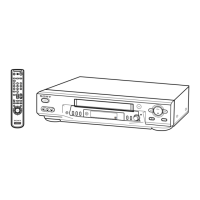
Removing the outer casing of the unit.

Block Diagrams

Overall Block Diagram

High-level functional overview of the VCR system.

Servo/System Control Block Diagram

Diagram of the servo and system control circuits.

Wiring Boards and Schematic Diagrams

Frame Schematic Diagram

Overall schematic layout of the VCR's circuits.

Printed Wiring Boards and Schematic Diagrams

Detailed diagrams of PCBs and their connections.

Interface and IC Pin Functions

MA-350 IC161 Pin Functions

Pin functions for IC161 on the MA-350 board (Video, Servo, Mechanism, Audio, Microprocessor).

Adjustments Procedures

Mechanical Adjustments

Procedures for physical adjustments of VCR parts.

Electrical Adjustments

Procedures for electrical calibration and tuning.
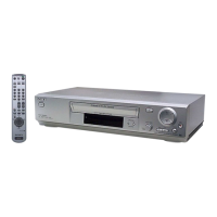
Related product manuals