5-4
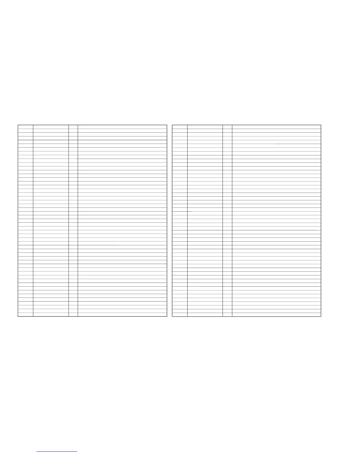
5-5. SERVO/SYSTEM/TIMER/TUNER CONTROL MICROPROCESSOR PIN FUNCTION (MA-323 BOARD IC161)
Pin No. Pin Name I/O Function
1 F MONO O TUNER Audio select signal
2 AN GND – Analog Ground
3 APC ERROR I APC ERROR Voltage input
4 DMS UP I Click Shuttle fowared/reverse signal input (DMS models only)
5 FUNC. KEY2 I Function Key Analog voltage input
6 TU AFT I AFT (Auto fine tuning signal input)
7 FUNC. KEY1 I Function Key Analog voltage input
8 POWER FAIL I Power failure detect signal input
9 DMS DOWN I Click Shuttle fowared/reverse signal input (DMS models only)
10 DEST I Destination set
11 S SENS I Supply end sensor signal input
12 T SENS I Take up end sensor signal input
13 VIDEO RF I Video RF Envelop input
14 AU RF I Hifi Audio Envelop input
15 AN 5V – Power supply
16 RESET I RESET signal input
17 3.58/4.43 O NTSC color freq. judge signal
18 PAL O “H”: PAL (Video block control signal)
19 SAP BILL OUT I MAIN/SAP judge input
20 STEREO OUT I STEREO/MONO judge input
21 MAIN/SAP O MAIN/SAP select signal
22 VCC – Power supply
23 AF SWP O AF switching pulse output
24 RF SWP O RF switching pulse output
25 CAP VS O Capstan error signal output
26 DRUM VS O Drum motor error signal output
27 QVD O Quasi VD pulse output
28 N.C. – Not used
29 H. AMPSW O “H”: A-DUB mode (CTL Amp. Gain. Coutrol)
30 N.C. – Not used
31 CTL (+) I/O CTL head signal Input/Output (rec mode)
32 CTL (–) I/O CTL head signal Input/Output (rec mode)
33 VSS (SERVO) – Ground
34 CTL-AMP1 I CTL Amp. Coutrol (Gain set)
35 CTL-AMP2 I CTL Amp. Coutrol (Gain set)
36 CTL-AMP3 I CTL Amp. Coutrol (Gain set)
37 CTL-AMP OUT O CTL Amp. Output (For Check)
38 DRUM FG I Drum FG Schmitt amp. input
39 DRUM PG I Drum PG Schmitt amp. input
40 CAP FG I Capstan FG Schmitt input
41 VCC (SERVO) – Power supply
42 VCC(OSD) – Power supply
43 CV IN I Composite Video signal input
44 VREF I Reference bias and clamp bias power pin
45 CV OUT O Composite Video signal output
46 N.C. – Not used
47 AFC LPF I AFC LPF pin
48 AFC OSC I AFC oscillator pin
49 VSS (OSD) – Ground
50 DOSC-IN I OSD dot clock oscillator (input)
Pin No. Pin Name I/O Function
51 DOSC-OUT O OSD dot clock oscillator (output)
52 4FSC-OUT O OSD 4fsc oscillator terminal (output)
53 4FSC-IN I OSD 4fsc oscillator terminal (input)
54 CSYNC I Composite Sync signal input
55 REC PRF I Erasing protection tab. Cassette in detection
56 IIC DATA O EEP ROM, Hifi IC, Tuner/Serial communication signal (IIC DATA)
57 IIC CLOCK O EEP ROM, Hifi IC, Tuner/Serial communication signal (IIC CLOCK)
58 DRUM QR O Drum motor step driving
59 AF REC O “H” output when Hifi audio REC
60 AF REC P O “L” output when Hifi audio REC pause
61 TV/VTR O RF output control
62 SSB CLOCK (VIDEO) O Video, Video Amp. Serial communication signal (CLOCK)
63 SSB DATA (VIDEO) O Video, Video Amp. Serial communication signal (DATA)
64 BLUE BACK O OSD block control signal output
65 APC PWM O APC PWN signal
66 CAP TRQ PWM O Capstan TRQ PWN output
67 TA MUTE O “H” output when Tuner mute
68 TEST I Fixed to Ground
69 32kHz (IN) I Timer Clock terminal (32kHz)
70 32kHz (OUT) O Timer Clock terminal (32kHz)
71 VSS – Ground
72 10MHz (IN) I System clock terminal (10MHz)
73 10MHz (OUT) O System clock terminal (10MHz)
74 END LED O Top/End LED ON/OFF control
75 REC P O “L” output when REC pause mode
76 IN SEL 1 O LINE-INPUT selection control signal-1
77 IN SEL 2 O LINE-INPUT selection control signal-2
78 OSD SEL – Not used
79 A MUTE O “H” Audio mute signal outout
80 WRITE CONT O EEPROM write timing control
81 EP. LP O “H” : “LP/EP” mode
82 REMOCON I Remote control signal (SIRCS) input
83 CAM O CAM motor control
84 MODE 1 I Mechanism section CAM encoder input (data1)
85 MODE 2 I Mechanism section CAM encoder input (data2)
86 MODE 3 I Mechanism section CAM encoder input (data3)
87 MODE 4 I Mechanism section CAM encoder input (data4)
88 T REEL I T side reel FG input
89 S REEL I S side reel FG input
90 FLD CS O FIP driver chip select signal output
91 FUll ERASE O Full erase head on/off control signal
92 P CONT O Power Supply control signal
93 CAP RVS O Capstan reverse control signal H when Reverse
94 CAP QR O Capstan step driving
95 S CLOCK 0 O Serial communication signal (Serial clock)
96 S IN 0 I Serial communication signal (Data input)
97 S OUT 0 O Serial communication signal (Data output)
98 PLL CLOCK O TUNER PLL clock
99 TU ENABLE O TUNER PLL signal chip select
100 PLL DATA O TUNER PLL data