7-5 7-6 E
4. Overall Level Characteristic and Distortion Factor
Check
Purpose:
Check the record level, play level, and distortion factor against the
reference input.
Mode REC and PB (SP mode)
Signal 400 Hz, –7.5 dBs
Measurement point Audio output terminal
Measurement equipment Audio level meter and
distortion factor meter
Specified value Playback level: –7.5 ± 4 dBs
Distortion factor: 4% or less
Confirmation Method:
1) Supply an audio signal of 400 Hz, –7.5 dBs simultaneously to
both L and R channels of Audio Line Input.
2) Make recording
3) Play back a recorded portion.
4) Confirm that a playback level is –7.5 ± 4 dBs.
5) Confirm that a distortion factor is within 4%.
5. Overall S/N Check
Purpose:
Confirm that the S/N is within the specification.
Mode REC and PB (SP mode)
Signal Short
Measurement point Audio output terminal
Measurement equipment Audio noise meter
Specified value –46.0 dBs or less
Confirmation Method:
1) Connect both L and R channels of audio line input to the GND.
2) Start recording.
3) Play the recorded part to confirm that the noise is below –46.0
dBs.
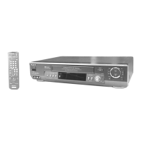
2-6. PARTS ARRANGEMENT DIAGRAM FOR ADJUSTMENTS
MA-323 BOARD (Side A)
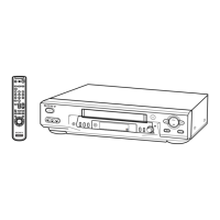
HS-921SF/921SF1 BOARD (Side A)
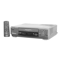
SR-708 BOARD (Side A)
RV201
CN201
6V ADJ
19
CN501
CN431
14
2
1
JS140
RV750
IC750
13
1
US MPX SEP
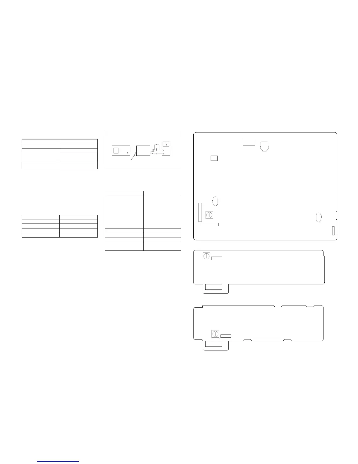
2-5. TUNER SYSTEM ADJUSTMENT
[Connection]
Fig. 7-2-6
2-5-1. Separation Adjustment (SLV-ED8)
Purpose:
Mixed audio signal separate Lch and Rch.
Mode E-E
Signal VIDEO:
color bar
(87.5% modulation)
AUDIO:
L 1 kHz 100% modulation
R no signal
ELECTRIC FIELD:
60–80 dBs/75 W Tem
Measurement point Pin !™ of IC750
Measurement equipment Audio level meter
Adjusting Element RV750
Specified value –9.9 ± 0.2 dBm
(700 ± 14 mVp-p)
47 k
VTR
Audio level
meter
Up channel
convertor
RF IN
RV201
CN201
6V ADJ
19