EasyManua.ls Logo

Sony SLV-EX90S User Manual

Sony SLV-EX90S
75 pages
To Next Page IconTo Next Page
Page #1 background imageLoading...
Page #1 background image
Argentina Model
SLV-EX50AR/EX80SAR/
EX90SAR
Brazil Model
SLV-EX50BR/EX80SBR/
EX90SBR
VIDEO CASSETTE RECORDER
* The abbreviations of EX50/EX80S and EX90S contained in this
service manual are indicated when these models are common to
all their corresponding models as given below.
EX50
Abbreviated
model name
All model
names
SLV-
EX80S EX90S
EX90SAR
EX90SBR
RMT-V312/V312A
SLV-EX50/EX80S/EX90S
EX80SAR
EX80SBR
EX50AR
EX50BR
SLV-EX90S
SERVICE MANUAL
123
456
789
0
VIDEO
g
S MECHANISM
Refer to the SERVICE MANUAL of VHS MECHANICAL
ADJUSTMENTS VI for MECHANICAL ADJUSTMENTS.
(9-921-647-11)
w
w
w
.
x
i
a
o
y
u
1
6
3
.
c
o
m
Q
Q
3
7
6
3
1
5
1
5
0
9
9
2
8
9
4
2
9
8
T
E
L
1
3
9
4
2
2
9
6
5
1
3
9
9
2
8
9
4
2
9
8
0
5
1
5
1
3
6
7
3
Q
Q
TEL 13942296513 QQ 376315150 892498299
http://www.xiaoyu163.com

Table of Contents

Question and Answer IconNeed help?

Do you have a question about the Sony SLV-EX90S and is the answer not in the manual?

Sony SLV-EX90S Specifications

General IconGeneral
BrandSony
ModelSLV-EX90S
CategoryVCR
LanguageEnglish

Summary

SECTION 1 GENERAL

Getting Started

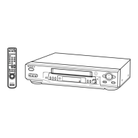
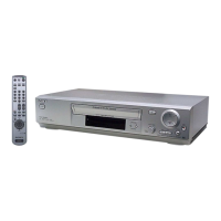
Initial setup for remote commander, hookups, RF unit, language, and channel presetting.

SECTION 2 DISASSEMBLY

Case, Front Panel Block Assembly

Procedure for disassembling the front panel and case.

DM-98, DI-81, and FJ-31 Boards

Disassembly steps for DM-98, DI-81, and FJ-31 boards.

Rear Panel

Instructions for removing the rear panel.

MA-402 Board

Steps to remove the MA-402 main board.

Mechanism Deck

Procedure for disassembling the mechanism deck.

Internal Views

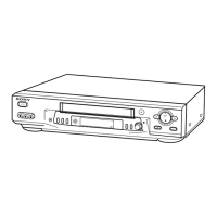
Illustrations showing internal components and their locations.

Circuit Boards Location

Identifies the location of key circuit boards like MA-402, FJ-31, DM-98, DI-81.

SECTION 3 BLOCK DIAGRAMS

Overall Block Diagram

Provides a high-level overview of the system's functional blocks.

Video Block Diagram

Illustrates the video signal path and processing within the VCR.

Servo/System Control Block Diagram

Details the servo and system control signal flow.

Audio Block Diagram

Shows the audio signal path and processing.

Tuner Block Diagram

Illustrates the tuner section's signal flow and connections.

Mode Control Block Diagram

Depicts the control signals for various operating modes.

Power Block Diagram

Shows the power supply circuitry and distribution.

SECTION 4 PRINTED WIRING BOARDS AND SCHEMATIC DIAGRAMS

Frame Schematic Diagram

Overall schematic showing connections between major assemblies.

MA-402 Board (Video, Audio Block)

Detailed schematic for the video and audio processing circuitry.

MA-402 Board (Servo/System Control)

Schematic detailing servo and system control functions.

MA-402 Board (Hi-Fi Audio)

Schematic for the Hi-Fi audio circuitry.

MA-402 Board (Tuner)

Schematic of the tuner section.

MA-402 Board (I/O)

Schematic showing input/output connections and controls.

MA-402 Board (Mode Control)

Schematic of the mode control circuitry.

MA-402 Board (Power Supply)

Schematic of the power supply section.

FJ-31 and DM-98 Boards

Printed wiring and schematic for FJ-31 and DM-98 boards.

DI-81 Board (Dial Timer)

Printed wiring and schematic for the DI-81 dial timer board.

SECTION 5 INTERFACE, IC PIN FUNCTION DESCRIPTION

System Control – Video Block Interface

Describes signals between system control and video block IC101.

System Control – Servo Peripheral Circuit Interface

Details signals between system control and servo IC101.

System Control – Mechanism Block Interface

Explains signals between system control and mechanism IC101.

System Control – Audio Block Interface

Describes signals between system control and audio IC101.

Servo/System Control, OSD Microprocessor Pin Function

Lists pin functions for servo, system control, and OSD microprocessor.

SECTION 6 ERROR CODE

Error Codes

Lists error codes and their descriptions for VCR malfunctions.

Mode Codes in Case of Error

Lists mode codes displayed during error conditions.

SECTION 7 ADJUSTMENTS

Mechanical Adjustments

Procedures for mechanical adjustments.

Electrical Adjustments

Covers pre-adjustment, power supply, servo, audio, and tuner electrical adjustments.

SECTION 8 REPAIR PARTS LIST

Exploded Views

Illustrated diagrams of parts for various sections of the VCR.

Electrical Parts List

Lists electrical components (resistors, capacitors, diodes, etc.) with part numbers.

Related product manuals