Do you have a question about the Sony SS-RG60 and is the answer not in the manual?
Procedures for detaching the panel and key boards from the front panel.
Explanation of the functions of various buttons on the main unit.
Step-by-step guide for disassembling the outer case components of the unit.
Procedure for removing the main and power amplifier boards.
Checks software version, FL tube, LED, keyboard, headphone, and volume.
Checks operations of Amplifier, TUNER, CD, and Tape sections.
Checks the S-curve waveform for CD player alignment.
Verifies the RF signal level for the CD player.
Electrical schematic for the BD section.
Electrical schematic for the Main section (part 1/5).
Electrical schematic for the Main section (part 2/5).
Electrical schematic for the Main section (part 3/5).
Electrical schematic for the Main section (part 4/5).
Electrical schematic for the Main section (part 5/5).
Electrical schematic for the Power Amp section.
Electrical schematic for the Panel section.
Electrical schematic for the Trans section.
Electrical schematic for the Driver section.
| Brand | Sony |
|---|---|
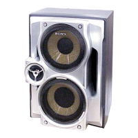
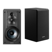
| Model | SS-RG60 |
| Category | Speaker System |
| Language | English |