Do you have a question about the Sony SS-TS503 and is the answer not in the manual?
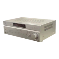
General specifications including power requirements, consumption, and dimensions.
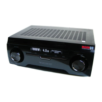
Details power output and total harmonic distortion for the C770 model.
Procedure to enter the system's diagnostic test mode for troubleshooting.
Details how to navigate and operate within the test mode menus.
Checks system controller status and diagnostic items.
Automatic adjustment of servo parameters for DVD-SL, CD, and DVD-DL discs.
Procedure to check for AC leakage from exposed metal parts to earth ground.
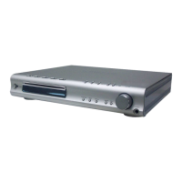
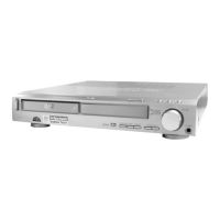
Identifies and describes the function of front and rear panel controls and connectors.
Explains the information displayed on the front panel during various operations.
Guidelines for safely handling the optical pick-up block to prevent electrostatic damage.
Instructions for DVD board replacement, including necessary adjustments and memory initialization.
Procedure to release the disc slot lock function for demonstration discs.
Step-by-step visual guide for disassembling the main unit components in order.
Detailed instructions for disassembling the front panel and side panels.
Procedures for removing and disassembling the mechanism deck unit.
Steps for disassembling and removing the DVD board from the unit.
Instructions for correctly installing the cam component for eject lock mechanism.
Steps for properly fitting and installing the stocker assembly components.
Overview of the test mode functionality and on-screen display usage.
Lists the specific test discs required for operating the self-diagnosis modes.
Manual control of servo functions and adjustments for design purposes.
Re-adjusting the servo circuit after component replacement, covering multiple disc types.
Procedure to check the RF signal waveform and level using an oscilloscope.
Visual representation of the RF servo signal path and component connections.
Detailed electrical schematic for the RF board.
Layout of components on the DVD board's component side.
Illustrations of typical signal waveforms measured on the RF board.
Exploded view of the main chassis and front panel sections.
Exploded view of additional front panel components.
Exploded view of the main mechanism deck assembly parts.
Exploded view of the optical pick-up unit and its related parts.
Detailed pinout and function description for the mechanism controller IC301.
Pinout and function description for the DSP/Servo Processor IC401.
Comprehensive list of electrical parts and components for the amplifier board.
Detailed specifications for the SS-CT551 center speaker unit.
Detailed specifications for the SS-TS551 front/rear speaker unit.
Detailed specifications for the SS-WS551 subwoofer unit.