SERVICE MANUAL
9-874-058-01 Sony Corporation
2002G0500-1 Home Audio Company
C 2002.07 Published by Sony Engineering Corporation.
Ver 1.0 2002.07
COMPACT AV SYSTEM
DAV-C770 DAV-C990
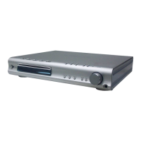
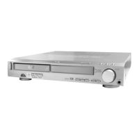
SACD/DVD RECEIVER HCD-C770 HCD-C990
FRONT SPEAKER SS-TS503 SS-TS551
CENTER SPEAKER SS-TS503 SS-CT551
REAR SPEAKER SS-TS503 SS-TS551
SUB WOOFER SS-WS503 SS-WS551
PACKAGE SPEAKER SS-WT503 SS-C990
US Model
Canadian Model
DAV-C770/C990
AEP Model
Australian Model
DAV-C770
•DAV-C770/C990 are composed of following models.
As service manuals are issued for each component model, please refer to them.
COMPONENT MODEL NAME
1-477-372-11 COMMANDER, STANDARD (RM-SS990)
1-754-060-13 ANTENNA (FM) (C770: AEP, Australian)
1-754-147-11 ANTENNA (FM) (C770: US, Canadian/C990)
1-754-149-11 LOOP ANT (AM)
1-769-108-11 CORD, CONNECTION (VIDEO CORD)
1-824-622-11 CORD (WITH CONNECTOR) (RED)
(for FRONT R SPEAKER)
1-824-622-21 CORD (WITH CONNECTOR) (PURPLE) (for SUB WOOFER)
1-824-622-31 CORD (WITH CONNECTOR) (WHITE)
(for FRONT L SPEAKER)
1-824-622-41 CORD (WITH CONNECTOR) (GRAY)
(for REAR R SPEAKER)
1-824-622-51 CORD (WITH CONNECTOR) (BLUE)
(for REAR L SPEAKER)
1-824-622-61 CORD (WITH CONNECTOR) (GREEN)
(for CENTER SPEAKER)
1-824-180-11 CORD, CONNECTION (21PIN ADAPTER) (AEP)
4-241-068-11 MANUAL, INSTRUCTION (ENGLISH) (C770)
4-241-068-21 MANUAL, INSTRUCTION (FRENCH) (C770: Canadian, AEP)
4-241-068-31 MANUAL, INSTRUCTION (GERMAN, SPANISH, DUTCH,
SWEDISH, ITALIAN, POLISH) (C770: AEP)
4-241-068-41 MANUAL, INSTRUCTION (DANISH, FINNISH,
PORTUGUESE) (C770: AEP)
4-241-068-51 MANUAL, INSTRUCTION (GREEK) (C770: AEP)
4-241-071-11 MANUAL, INSTRUCTION (ENGLISH) (C990)
4-241-071-21 MANUAL, INSTRUCTION (FRENCH) (C990: Canadian)
4-243-416-01 BATTERY COVER (for RM-SS990)
4-243-457-01 RUBBER (SPEAKER) (for SPEAKER)
PARTS LIST
Part No. Description Remark
DAV-C770/C990
SPECIFICATIONS
General
Power requirements
North American model: 120 V AC, 60 Hz
European model: 230 V AC, 50/60 Hz
Australian model: 220 – 240 V AC, 50/60 Hz
Power consumption 135
140 W (120 V AC) (DAV-C990)
W (120 V AC) 135 W (230 V AC) (DAV-C770)
1 W (120 V AC) 2 W (230 V AC) (at the Power Saving Mode)
Dimensions (approx.) 355 × 70 × 335 mm (14 × 2
7
/
8
× 13
1
/
4
inches: DAV-C770)
(14 × 2
7
/
8
× 15 inches: DAV-C990) (w/h/d) incl. projecting parts
Mass (approx.) 4.4 kg (9 lb 12 oz)
Operating temperature 5˚C to 35˚C (41˚F to 95˚F)
Operating humidity 5 % to 90 %
Supplied accessories
Design and specifications are subject to change without notice.
• Speakers (5)
• Subwoofer (1)
• AM loop antenna (1)
• FM wire antenna (1)
• Speaker cords (5m × 4, 15m × 2) (17ft. × 4, 50ft. × 2)
• Video cord (1)
• Remote Commander (remote) RM-SS990 (1)
• R6 (size AA) batteries (2)
• Foot pads (20)
• Speakers-connection and Installation (card) (1)
• 21-pin Adapter (1) (Only for the European models)