EasyManua.ls Logo

Sony ST-88 - FM Alignment: Stereo Separation; Stereo Separation Adjustment Procedure; Stereo Separation Test Equipment and Preparation

Sony ST-88
22 pages
Print Icon
To Next Page IconTo Next Page
To Previous Page IconTo Previous Page
Loading...
ST-88
ac
VTVM
oscilloscope
fm
oO
——“-"—
0
—
0
signal
ANTENNA
NORMAL
OUTPUT
IN
ma
er
generator
©
Jack
(J802)
Lo
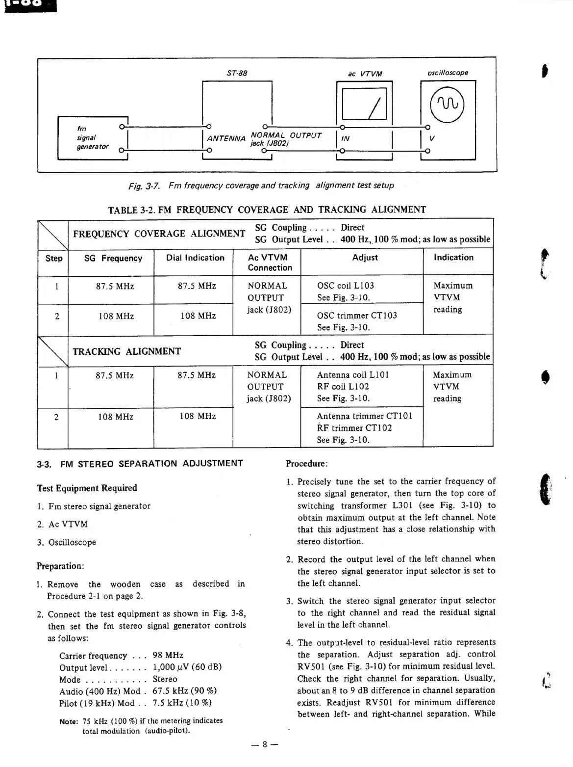
Fig.
3-7.
Fm
frequency
coverage
and
tracking
alignment
test
setup
TABLE
3-2.
FM
FREQUENCY
COVERAGE
AND
TRACKING
ALIGNMENT
SG
Coupling.....
re
SG
Output
Level
..
400
Hz,
100
%
mod;
as
low
as
possible
Step
SG
Frequency
Dial
Indication
Ac
VTVM
Adjust
Indication
Connection
87.5
MHz
87.5
MHz
NORMAL
OSC
coil
L103
Maximum
OUTPUT
See
Fig.
3-10.
VTIVM
2
108
MHz
108
MHz
jack
(J802)
FREQUENCY
COVERAGE
ALIGNMENT
reading
OSC
trimmer
CT103
See
Fig.
3-10.
SG
Coupling.....
Direct
SG
Output
Level
..
400
Hz,
100
%
mod;
as
low
as
possible
~~
TRACKING
ALIGNMENT
87.5
MHz
87.5
MHz
NORMAL
OUTPUT
jack
(J802)
108
MHz
108
MHz
3-3.
FM
STEREO
SEPARATION
ADJUSTMENT
Maximum
VTVM
reading
Antenna
coil
L101
RF
coil
L102
See
Fig.
3-10.
Antenna
trimmer
CT101
RF
trimmer
CT102
See
Fig.
3-10.
Procedure:
1.
Precisely
tune
the
set
to
the
carrier
frequency
of
stereo
signal
generator,
then
turn
the
top
core
of
switching
transformer
L301
(see
Fig.
3-10)
to
obtain
maximum
output
at
the
left
channel.
Note
that
this
adjustment
has
a
close
relationship
with
stereo
distortion.
Test
Equipment
Required
1,
Fm
stereo
signal
generator
2.
Ac
VTVM
3.
Oscilloscope
2.
Record
the
output
level
of
the
left
channel
when
the
stereo
signal
generator
input
selector
is
set
to
the
left
channel.
Preparation:
1.
Remove
the
wooden
case
as
described
in
Procedure
2-1
on
page
2.
k
: ;
a
3.
Switch
the
stereo
signal
generator
input
selector
.
Connect
the
test
equipment
as
shown
in
Fig.
3-8,
then
set
the
fm
stereo
signal
generator
controls
as
follows:
Carrier
frequency
...
98
MHz
Output
level.......-
1,000
nV
(60
dB)
Mode
........-.--
Stereo
Audio
(400
Hz)
Mod
.
67.5
kHz
(90
%)
Pilot
(19
kHz)
Mod...
7.5
kHz
(10
%)
Note:
75
kHz
(100
%)
if
the
metering
indicates
total
modulation
(audio-pilot).
to
the
right
channel
and
read
the
residual
signal
level
in
the
left
channel.
.
The
output-level
to
residual-level
ratio
represents
the
separation.
Adjust
separation
adj.
control
RV501
(see
Fig.
3-10)
for
minimum
residual
level.
Check
the
right
channel
for
separation.
Usually,
about
an
8
to
9
dB
difference
in
channel
separation
exists.
Readjust
RV501
for
minimum
difference
between
left-
and
right-channel
separation.
While
Ww
r