EasyManua.ls Logo

Sony ST-A35L - Page 13

Sony ST-A35L
20 pages
Print Icon
To Next Page IconTo Next Page
To Previous Page IconTo Previous Page
Loading...
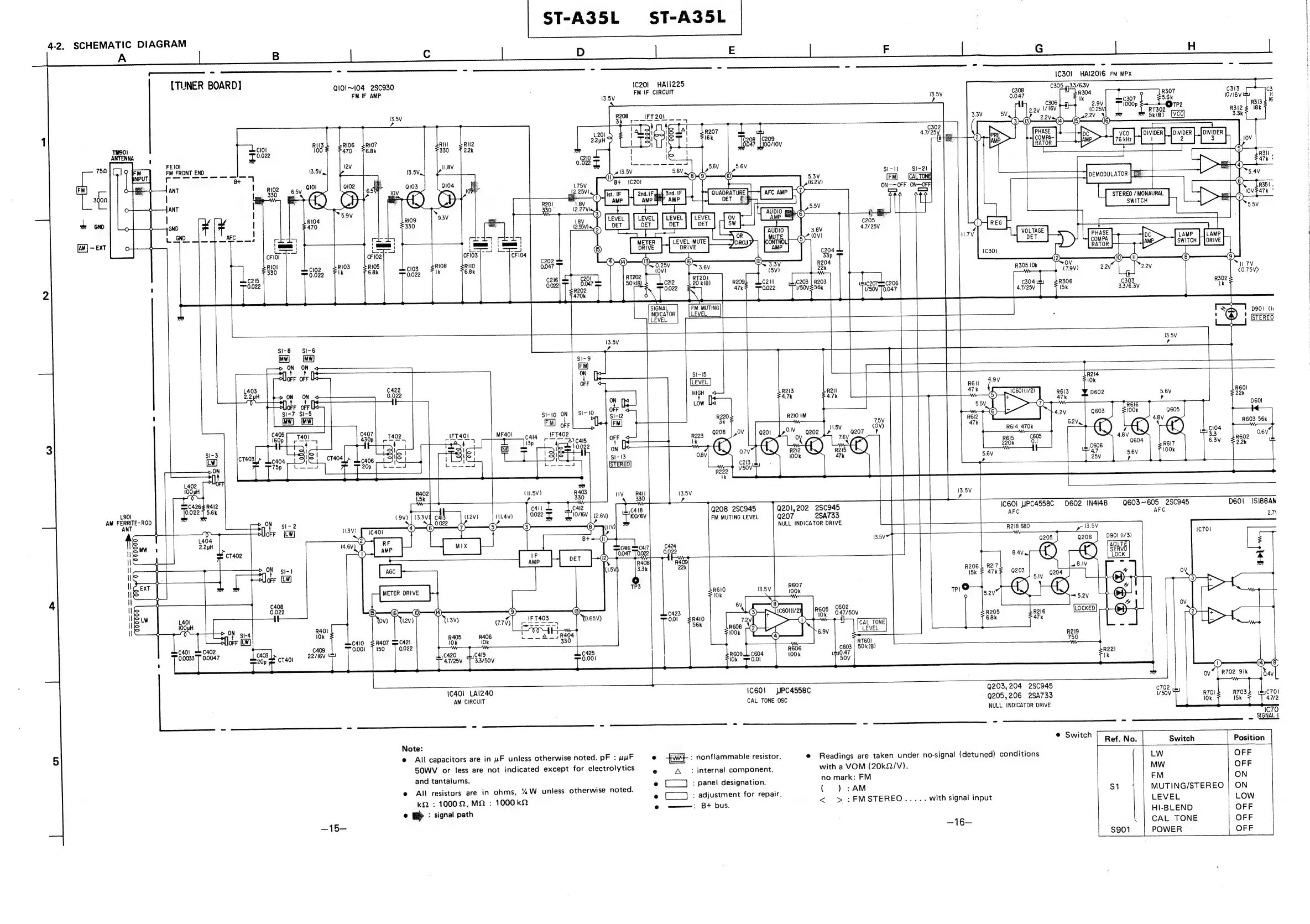
ST-A35L
ST-A35L
4-2,
SCHEMATIC
DIAGRAM
=
=
2
P
E
F
|
G
___H
eee
me
/-:
IC301
HAI2Z0OI6
FM
MPX
[TUNER
BOARD]
QIO1~104
2SC930
ic20l
HAII225
FM
IF
AMP
FM
IF
CIRCUIT
13.5V
ae
5k
(B)
RII3
Cl0l
100
aoe
FE
101
'
FM
FRONT
END
13.5V
‘
ANT
|
ANT
|
GND
GND
4.7/25V
C215
0.022
4.7/25V
(9)
Nu7V
<0.75V>
R302
ik
D901
(I
®)
'
crenro
SI-8
SI-6
[Mw]
[MW]
>
ON
ON
lotr
ofr
L
PUOFF
OFF
SI-15
aes
LEVEL
2.2
pH
>
ON
ON
<
R213
47k
R60!
ae
ws
a
|
es
|
4.7k
6)
ede
22k
ww}
[a
S110
OF
ep
si
R210
1M
ach
LO
i
otF
U
Ra
|
R603
56k
caig
__
[F402
R6I4
470k
139
AT
CIS
c605
|
0.6V
;
:
'Cm
|
0022
BORO.
Be?
SI-3
aie
2.2k
jel
be
ed
:
R402
(u.5V)
R403
ina
R412
Ka
‘
x
id
022
F
5.6k
C4
C4l2
api
ac
|
Q208
2S¢945
Q201,202
2SC945
IC60l
HPC4558C
D602
IN4I48
Q603~605
2SC945
D601
ISIBBAN
.!
(9v)
|
(33V¥
C413
(1.2V)
(11.4V)
0.022
lO/IGV
|
(2.6
:
an
le
Bee
D
i
Si-
2
<1
0.022
i
™
Na
ee
te
piles
Ty
yf]
my
oc
Lor
R218
680
yo
13.5V
eae
D90I
(1/3)
BON
stot
al
;
cu
ee
3
iz
0.022
ee
Cs
77%)
|
ie
iow
ion
R405
R406
EAE
a
PUorF
[LW]
Ok
10k
C401
=
C402
as
C409
0.0033
J"
0.0047
Sor
a
CTAO
22/16V
OW)
(48
|
Faro
ok
|
0.4V
1C401
LAI2Z40
IC601
PC4558C
Q203,204
250945
C702
AM
CIRCUIT
CAL
TONE
OSC
9205,
206
2SA735
oe
a2
NULL
INDICATOR
DRIVE
sae
IC70
Note:
@
All
capacitors
are
in
uF
unless
otherwise
noted.
pF
:
uuF
©
fw}
:
nonflammable
resistor.
e
Readings
are
taken
under
no-signal
(detuned)
conditions
SOWV
or
less
are
not
indicated
except
for
electrolytics
e
3A:
internal
component.
with
a
VOM
(20k2/V).
and
eo
.
ai
be
tas
deren
e
[___]
:
panel
designation.
no
mark:
FM
FM
nless
rwi
e
All
resistors
are
in
ohms,
“ZW
unless
oO
©
(1)
;
adjustment
for
repair.
(
)
:
AM
a
.
MUTING/STEREO
kQ
:
10002,M2
:
1000
k2
.
nae
pie
<
>
:FMSTEREO.....
with
signal
input
LEVEL
HI-BLEND
:
signal
path
2G
~16—
CAL
TONE
POWER
eran
SK
3
;
4
3
A
;
3
OP
Te
tar
Ne