The provided document is a service manual for the Sony ST-JX431, an FM stereo/FM-AM tuner. It also references the ST-JX421 and ST-JX521 models, indicating that the ST-JX431 is largely similar to the previously produced ST-JX421 and that the ST-JX421 and ST-JX521 are tuner sections within larger systems (SEN-421CD/SEN-421 and SEN-521/SEN-721, respectively). This manual focuses on the service and maintenance aspects of the device rather than a comprehensive user guide.
Function Description
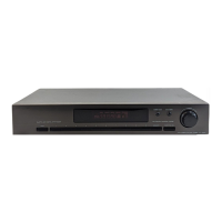
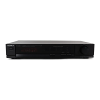
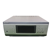
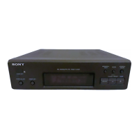
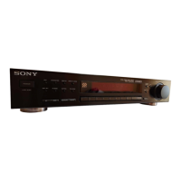
The Sony ST-JX431 is an FM stereo/FM-AM tuner designed to receive radio broadcasts. It functions as a component within a larger audio system, specifically noted as the tuner section in the SEN-431CD. Its primary role is to tune into and process both FM stereo and AM radio signals, delivering them to an amplifier or other audio components for playback. The device includes controls for tuning, band selection (FM/AM), memory functions for preset stations, and a display window to show tuning information.
Important Technical Specifications
The service manual provides detailed specifications for the FM tuner section and AM tuner section, primarily for the ST-JX421/JX521 models, which are stated to be very similar to the ST-JX431.
FM Tuner Section:
- Tuning Range: 87.5 – 108 MHz
- Antenna Terminals: 75 ohms unbalanced, 300 ohms balanced
- Intermediate Frequency: 10.7 MHz
- Sensitivity (at 50 dB quieting):
- 22.1 dBf, 7 µV (mono)
- 42.1 dBf, 70 µV (stereo)
- Usable Sensitivity (IHF): 19.5 dBf, 5 µV
- Signal-to-Noise Ratio (at 75 kHz deviation):
- 80 dB (mono)
- 75 dB (stereo)
- Harmonic Distortion (at 1 kHz):
- 0.3% (mono)
- 0.5% (stereo)
- Separation (at 1 kHz): 35 dB
- Frequency Response: 30 Hz – 15 kHz ±2 dB
- Selectivity (at 400 kHz): 55 dB
- AM Suppression Ratio: 54 dB
- Image Response Ratio: 50 dB
- IF Response Ratio: 90 dB
- Spurious Response Ratio: 70 dB
- Automatic Tuning Threshold: 17.8 µV (30 dBf)
- Output (at 75 kHz deviation): 775 mV, 4.7 kohms
AM Tuner Section:
- Tuning Range:
- US, Canadian model: 530 – 1,710 kHz (10 kHz) / 531 – 1,710 kHz (9 kHz)
- E model: 531 – 1,602 kHz
- Antenna: AM loop antenna, External antenna terminal
- Intermediate Frequency: 450 kHz
- Usable Sensitivity: AM loop antenna: 500 µV/m (999 kHz or 1,000 kHz)
- Signal-to-Noise Ratio: 54 dB
- Harmonic Distortion: 0.5%
- Selectivity:
- 35 dB (9 kHz)
- 38 dB (10 kHz)
General Specifications (ST-JX521):
- Power Requirements:
- US, Canadian model: 120V AC, 60 Hz
- E model: 240V AC, 50 Hz
- Power Consumption: 8W (ST-JX521)
- AC Outlet (U.S.A. model only): 1 unswitched, 120W/1 A max.
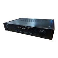
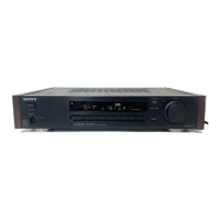
- Dimensions: Approx. 430 x 80 x 295 mm (w/h/d) (17 x 3¼ x 11⅝ inches)
- Weight:
- ST-JX421: Approx. 2.1 kg (4 lb 11 oz)
- ST-JX521: Approx. 2.6 kg (5 lb 12 oz)
Accessories Supplied (ST-JX421):
- Flat cord with 11-5-5-pin connectors (1), connected to TC-W311.
- Flat cord with 9-9-pin connectors (1)
- Remote commander RM-S102 (1)
- Sony batteries SUM 3 (NS) (2)
Accessories Supplied (ST-JX521):
- Remote control cord (1)
- Audio connecting cord (1)
- AM loop antenna (1)
- FM loop antenna (1)
Usage Features
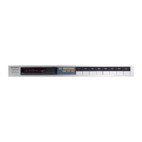
Based on the "Location of Controls" and "Connections" sections, the ST-JX431 (and similar models) offers several user-friendly features:
- Power Switch: To turn the unit on/off (ST-JX521 only, implying ST-JX431 might be powered via the main system).
- SHIFT Button: Likely used for accessing secondary functions of other buttons.
- Display Window: Provides visual feedback on tuning frequency, station information, and other settings.
- MEMORY SCAN Button: Allows users to scan through and preview preset stations.
- AUTO TUNING Button: Facilitates automatic scanning and stopping at receivable stations.
- TUNING Control: A knob for manual tuning of radio frequencies.
- BAND FM/AM Selector: To switch between FM and AM radio bands.
- MEMORY Button: Used to store current stations into memory presets.
- Numeric Buttons: For direct access to preset stations.
- Antenna Connections: Supports both 75-ohm unbalanced and 300-ohm balanced FM antennas, and includes terminals for an AM loop antenna and an external AM antenna.
- System Control: Features flat remote control cords for integration with other Sony audio components (like amplifiers and tape decks) for unified remote operation.
- AC Outlet (U.S.A. model only): An unswitched AC outlet to power another audio component with a power consumption limit of 120W/1A max, controlled by the tuner's power switch.
- AM Tuning Interval Change: The device allows users to switch the AM tuning interval between 10 kHz (factory preset for US/Canadian models) and 9 kHz (for E models). This is done by a specific sequence involving the POWER switch and TUNING knob. Note that changing this interval will erase all preset stations.
Maintenance Features
The service manual is primarily focused on maintenance and repair, highlighting several key aspects:
- Safety Check-Out: After any repair, a safety check is mandatory, including a leakage test on exposed metal parts (antenna terminals, metal trim, knobs, screws). Leakage current must not exceed 0.5 mA (500 microamperes). Methods for measuring leakage are provided, including using a commercial leakage tester, a battery-operated AC milliammeter, or an AC voltmeter.
- Safety-Related Components: Components identified with a "A" mark or dotted line with a "A" mark on schematic diagrams and parts lists are critical for safety. These must be replaced only with specified Sony parts to ensure continued safe operation.
- Electrical Adjustments: Detailed procedures for electrical adjustments are provided, including:
- FM Discriminator Alignment (NULL check): Involves tuning to 98 MHz and adjusting T21 for 0V reading on a VOM.
- FM Tuning Level Adjustment: Involves tuning to 98 MHz and adjusting RV24 until the TUNED LED illuminates.
- AM Tuned Indication Lighting Level Adjustment: Involves tuning to a specific AM frequency (1,050 kHz for US/Canadian, 999 kHz for E models) and adjusting RV22 until the TUNED LED illuminates.
- Diagrams and Parts Lists: The manual includes comprehensive diagrams (printed wiring boards, schematic diagrams, semiconductor lead layouts, waveforms) and an electrical parts list, which are essential for troubleshooting and component replacement.
- Component Identification: Clear instructions are given for identifying components, including capacitor values (µF, pF), resistor values (ohms, 1/4W, 1/2W, 1/10W), and semiconductor types.
- Waveform Information: Waveforms are provided with respect to ground under no-signal (detuned) conditions, with voltage readings taken with a VOM (input impedance 10MΩ) and waveforms with an oscilloscope.
- Exploded View: An exploded view diagram is included to assist with mechanical disassembly and reassembly, along with a list of hardware parts.
- Part Stocking Information: Notes indicate that items marked "*" are not typically stocked and may require a delay for ordering. Mechanical parts without reference numbers in the exploded views are not supplied.
The manual emphasizes the importance of using genuine Sony parts for safety-critical components and provides detailed instructions for both electrical and mechanical servicing.