Do you have a question about the Sony ST-S770ES and is the answer not in the manual?
Details about the unit's general specifications, including circuit system, power, dimensions, weight, and accessories.
Technical performance specifications for the FM reception band.
Technical performance specifications for the AM reception band.
Information on identifying the specific model and its regional variations.
Describes the digital control of the tuning knob for accurate frequency selection.
Explains the PLL IC's role in improving signal-to-noise ratio by using high comparison frequencies.
Highlights the pure sound achieved by stopping the micro-computer clock during reception.
Details the WOIS and WODD systems for optimal IF waveform and low distortion.
Explains the automatic tuning of up to four memorized stations in sequence.
Alerts users about critical components identified for safe operation and replacement.
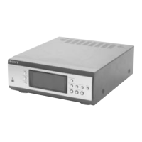
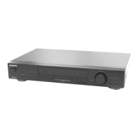
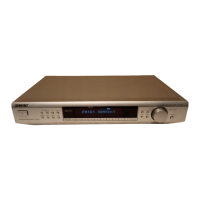
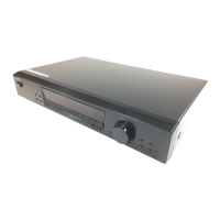
Details the placement and purpose of all front panel controls and indicators.
Step-by-step guide for manually selecting radio stations using the tuning knob.
Instructions for using the automatic scan feature to find stations.
Process for saving desired radio station frequencies and settings into memory.
Methods for recalling and listening to previously stored radio stations.
How to automatically cycle through memorized stations.
How to manually step through memorized stations.
Detailed pin assignments and functions for the main system controller IC.
Comprehensive list of pin names, I/O, active states, and descriptions for IC601.
Instructions for entering and using the test mode for system checking.
Visual representation of the tuner's internal circuitry and signal flow.
Procedure for adjusting the control voltage for proper tuner operation.
Steps to minimize distortion in the tuner's detection circuits.
Adjusting FM muting sensitivity and narrow IF gain for optimal reception.
Procedures for optimizing stereo signal output and channel separation.
Layout diagrams showing component placement on the circuit boards.
Detailed circuit schematics illustrating the tuner's electronic connections.
Visual representations of signal waveforms at various test points.
Functional block diagrams for key integrated circuits used in the tuner.
Diagrams showing the physical pin configurations of semiconductor components.
Exploded view illustrating the breakdown of the tuner's outer cabinet components.
Exploded view detailing the internal chassis and component mounting.
Comprehensive list of electronic components organized by their respective circuit boards.
List of hardware components such as screws, nuts, and washers used in assembly.
| Brand | Sony |
|---|---|
| Model | ST-S770ES |
| Category | Car Receiver |
| Language | English |