EasyManua.ls Logo

Sony HCD-S20 Service Manual

Sony HCD-S20
40 pages
To Next Page IconTo Next Page
Page #1 background imageLoading...
Page #1 background image
SERVICE MANUAL
Sony Corporation
Published by Sony Techno Create Corporation
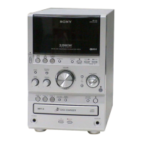
HCD-S20
SPECIFICATIONS
COMPACT DISC RECEIVER
9-893-739-01
2013D33-1
©
2013.04
E Model
Ver. 1.0 2013.04
HCD-S20 is compact disc receiver in CMT-S20.
Model Name Using Similar Mechanism NEW
Mechanism Type TDL-5
Amplier section
Power output (rated): 4 watts + 4 watts
(8 ohms at 1 kHz, 1% THD)
Continuous RMS power output (reference):
5 watts + 5 watts (8 ohms at 1 kHz, 10% THD)
Input
AUDIO IN (stereo mini jack): Sensitivity 1 V,
impedance 50 kilohms
Outputs
SPEAKERS: Accepts impedance of 8 ohms
CD player section
System: Compact disc and digital audio system
Laser Diode Properties
Emission Duration: Continuous
Laser Output*: Less than 44.6μW
* This output is the value measurement at a distance of
200mm from the objective lens surface on the Optical
Pick-up Block with 7mm aperture.
Frequency response: 20 Hz 20 kHz
Signal-to-noise ratio: More than 90 dB
Dynamic range: More than 90 dB
Tuner section
FM stereo, FM superheterodyne tuner
Antenna: FM lead antenna
Tuning range: 87.5 MHz 108.0 MHz (50 kHz
step)
USB section
(USB) port: Type A, maximum current 500 mA
Supported audio formats
Supported bit rate:
MP3 (MPEG 1 Audio Layer-3): 32 kbps
320 kbps, VBR
WMA: 32 kbps 192 kbps, VBR
Sampling frequencies:
MP3 (MPEG 1 Audio Layer-3): 32/44.1/48 kHz
WMA: 44.1 kHz
General
Except Korean model:
Power requirements: AC 120 V 240 V, 50/60 Hz
Korean model:
Power requirements: AC 220 V 240 V, 50/60 Hz
Power consumption: 18 watts
Dimensions (W/H/D, including largest
protrusions) (excl. speakers):
Approx. 170 mm × 133 mm × 240 mm
Mass (excl. speakers): Approx. 1.3 kg
Quantity of the main unit: 1 piece
Design and specifications are subject to change
without notice.
Standby power consumption: 0.5 W
Halogena ted flame retardants are not used in
the certain printed wiring boards.

Questions and Answers:

Sony HCD-S20 Specifications

General IconGeneral
CategoryCar Receiver
BrandSony
ModelHCD-S20
TypeCD Receiver
CD PlayerYes
Radio TunerAM/FM
MP3 PlaybackYes
Remote ControlYes
DisplayLCD
Output Power45W x 4 channels

Summary

Specifications Overview

System Specifications

Details on Amplifier, CD, Tuner, and USB sections.

Supported Audio Formats

Lists supported audio codecs and bit rates for MP3 and WMA.

General Unit Specifications

Covers power requirements, consumption, dimensions, and mass of the unit.

Servicing Notes

Handling Precautions

Guidelines for handling optical pick-up, laser diodes, and unleaded solder.

Repair and Test Disc Information

Notes on board repair, part replacement, and required test discs.

Disassembly Procedures

Top Cover and Rear Panel Removal

Steps to remove the top cover and rear panel assembly.

Front Panel and Loader Mechanism Removal

Procedures for disassembling the front panel and loader mechanism.

Internal Board Removal

Steps for removing VFD, USB, Main, and Power boards.

Test Modes

Software Version Check

Procedure to verify the MCU and MPEG IC software versions.

Tray Lock and Panel Test

How to lock the disc tray and test the VFD display functionality.

Factory Reset Procedure

Steps to clear all preset data and return the unit to initial conditions.

Electrical Checks

RF Signal Waveform Check

Procedure for checking the CD player's RF signal using an oscilloscope.

Troubleshooting Guides

Operation Check Flow

Step-by-step troubleshooting for basic operation issues.

Error Display Diagnosis

Diagnosing issues based on VFD error messages like OVER CURRENT or PROTECT.

Diagrams and Schematics

System Block Diagram

Overall system architecture illustrating component interactions.

Board Component Layouts

Component layout and connections for Main, Key, USB, and VFD boards.

Main Board Schematics & PWBs

Detailed circuit diagrams and printed wiring board layouts for the main board.

Other Board Schematics & PWBs

Diagrams for USB, VFD, Key, and Power boards, including PWBs.

Exploded Views

Top Cover Assembly Exploded View

Breakdown of the top cover assembly and related parts.

Chassis Internal Components Exploded View

Detailed parts breakdown of the main chassis and internal components.

Front Panel Assembly Exploded View

Exploded view of the front panel assembly, including controls and display.

Related product manuals