SERVICE MANUAL
Amplier section
DIN power output (rated):
60 + 60 watts (4 ohms at 1 kHz, DIN)
Continuous RMS power output
(reference): 75 + 75 watts (4 ohms at
1 kHz, 10% THD)
Inputs:
AUDIO IN (stereo mini jack):
voltage 250 mV, impedance 47
kilohms
(USB) port: Type A, maximum
current 500 mA
Outputs:
PHONES (stereo mini jack): accepts
headphones of 8 ohms or more
SPEAKER: accepts impedance of
4 ohms
Bluetooth section (HCD-HX5/HX7)
Communication system:
Bluetooth Standard version 2.0
Output:
Bluetooth Standard Power Class 2
Maximum communication range:
Line of sight approx. 10 m
1)
Frequency band:
2.4 GHz band (2.4000 GHz –
2.4835 GHz)
Modulation method:
FHSS
Compatible Bluetooth proles
2)
:
A2DP (Advanced Audio Distribution
Profile)
AVRCP (Audio Video Remote
Control Profile)
Su pp or t ed codecs:
Receive: SBC (Sub Band Codec), MP3
Transmit: SBC (Sub Band Codec)
1)
The actual range will vary depending on
factors such as obstacles between devices,
magnetic fields around a microwave oven,
static electricity, reception sensitivity,
antenna’s performance, operating system,
software application, etc.
2)
Bluetooth standard proles indicate the
purpose of Bluetooth communication
between devices.
USB section (HCD-HX3/HX5)
Supported bit rate
MP3 (MPEG 1 Audio Layer-3):
32 – 320 kbps, VBR
ATRAC: 48 – 352 kbps
(ATRAC3plus), 66/105/132 kbps
(ATRAC3)
WMA: 32 – 192 kbps, VBR
AAC: 48 – 320 kbps
Sampling frequencies
MP3 (MPEG 1 Audio Layer-3):
32/44.1/48 kHz
ATRAC: 44.1 kHz
WMA: 44.1 kHz
AAC: 44.1 kHz
CD player section
System: Compact disc and digital audio
system
Laser Diode Properties
Emission duration: continuous
Laser Output*: Less than 44.6µW
* This is output is the value measurement
at a distance of 200mm from the
objective lens surface on the Optical
Pick-up Block with 7mm aperture.
Frequency response: 20 Hz – 20 kHz
Signal-to-noise ratio: More than 90 dB
Dynamic range: More than 90 dB
Tuner section
FM stereo, FM/AM superheterodyne tuner
FM tuner section:
Tuning range
US, Canadian models: 87.5 – 108.0 MHz
(100 kHz step)
Other models: 87.5 – 108.0 MHz
(50 kHz step)
Antenna: FM lead antenna
Antenna terminals: 75 ohms unbalanced
Intermediate frequency: 10.7 MHz
AUDIO POWER SPECIFICATIONS
– HCD-HX7 –
– HCD-HX7 –
– HCD-HX5 –
– HCD-HX3 –
POWER OUTPUT AND TOTAL
HARMONIC DISTORTION:
(The United States model only)
With 6 ohm loads, both channels driven,
from 120 – 10,000 Hz; rated 50 watts per
channel minimum RMS power, with no
more than 10% total harmonic distortion
from 250 milliwatts to rated output.
Continuous RMS power output
(reference): 50 + 50 watts (6 ohms at
1 kHz, 10% THD)
Inputs:
AUDIO IN (stereo mini jack):
voltage 250 mV, impedance 47
kilohms
Outputs:
PHONES (stereo mini jack): accepts
Canadian, Australian, Korean models:
European model:
headphones of 8 ohms or more
SPEAKER: accepts impedance of
6 ohms
DIN power output (rated):
60 + 60 watts (4 ohms at 1 kHz, DIN)
Continuous RMS power output
(reference): 75 + 75 watts (4 ohms at
1 kHz, 10% THD)
Music power output (reference):
75 + 75 watts (4 ohms at 1 kHz, 10%
THD)
Canadian model:
DIN power output (rated): 40 + 40
watts (6 ohms at 1 kHz, DIN)
Continuous RMS power output
(reference): 50 + 50 watts (6 ohms at
1 kHz, 10% THD)
European model:
DIN power output (rated): 40 + 40
watts (6 ohms at 1 kHz, DIN)
Continuous RMS power output
(reference): 50 + 50 watts (6 ohms at
1 kHz, 10% THD)
Music power output (reference): 50 +
50 watts (6 ohms at 1 kHz, 10% THD)
Inputs:
AUDIO IN (stereo mini jack):
voltage 250 mV, impedance
47 kilohms
(USB) port: Type A, maximum
current 500 mA
Outputs:
PHONES (stereo mini jack): accepts
headphones of 8 ohms or more
SPEAKER: accepts impedance of
6 ohms
Model Name Using Similar Mechanism NEW
Base Unit Name HCD-HX7 BU-K6BD90-WOD
HCD-HX3/HX5 BU-K6BD90U-WOD
Optical Pick-Up Block Name KSM-213DCP
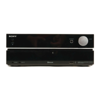
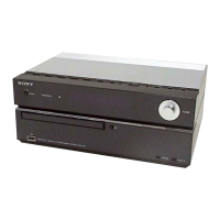
COMPACT DISC RECEIVER
HCD-HX3/HX5/HX7
SPECIFICATIONS
9-887-618-01
2007C05-1
© 2007.03
Sony Corporation
Personal Audio Division
Published by Sony Techno Create Corporation
• HCD-HX3 is the amplifier, USB, CD player
and tuner section in CMT-HX3.
• HCD-HX5 is the amplifier, bluetooth, USB,
CD player and tuner section in CMT-HX5BT.
• HCD-HX7 is the amplifier, bluetooth, CD
player and tuner section in CMT-HX7BT.
Photo: HCD-HX3
Ver. 1.0 2007.03
US Model
HCD-HX7
Canadian Model
AEP Model
HCD-HX3/HX5
UK Model
Australian Model
Korean Model
HCD-HX5
– Continued on next page –
• The Bluetooth word mark and logos are owned by the Bluetooth SIG, Inc.
and any use of such marks by Sony Corporation is under license. Other
trademarks and trade names are those of their respective owners.
• “WALKMAN” and “WALKMAN” logo are registered trademarks of Sony Corporation.
• MICROVAULT is a trademark of Sony Corporation.
• ATRAC, ATRAC3, ATRAC3plus and their logos are trademarks of Sony Corporation.
• U.S. and foreign patents licensed from Dolby Laboratories.
• MPEG Layer-3 audio coding technology and patents licensed from
Fraunhofer IIS and Thomson.
• The XM name and related logos are registered trademarks of XM Satellite Radio Inc.
• (c) 2006 SIRIUS Satellite Radio Inc. “SIRIUS” and the SIRIUS dog logo
are registered trademarks of SIRIUS Satellite Radio Inc.
TM ®
• and marks are omitted in this manual.