64
HCD-HX3/HX5/HX7
SECTION 7
EXPLODED VIEWS
Ref. No. Part No. Description Remark
Ref. No. Part No. Description Remark
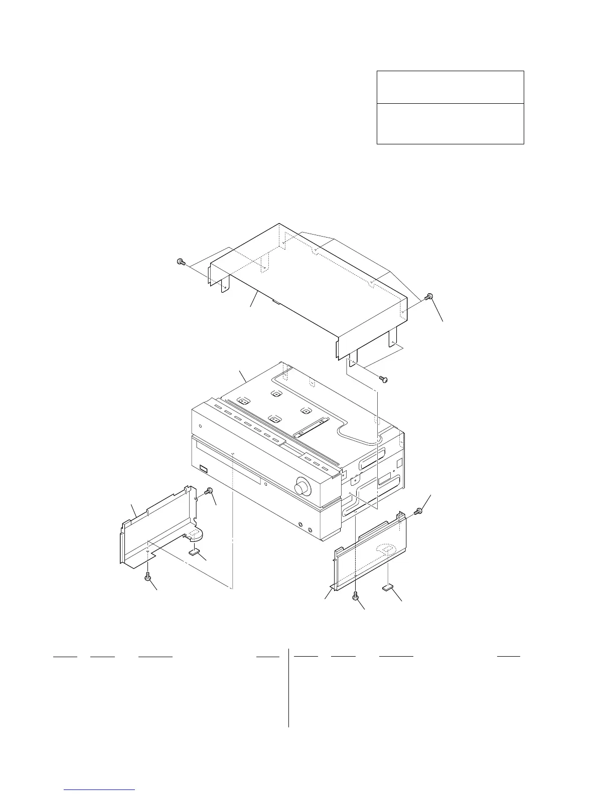
1 3-198-753-11 FOOT (FELT)
2 2-895-132-01 PANEL (SIDE R) (HX3/HX5)
2 2-895-132-11 PANEL (SIDE R) (HX7)
3 2-895-131-01 PANEL (SIDE L) (HX3/HX5)
3 2-895-131-11 PANEL (SIDE L) (HX7)
4 2-895-129-01 PANEL (TOP) (HX3: AEP/HX5: AEP, UK)
4 2-895-129-11 PANEL (TOP) (HX3: CND/HX5: CND, AUS, KR)
4 2-895-129-21 PANEL (TOP) (HX7)
5 7-685-871-01 SCREW +BVTT 3X6 (S) (HX3/HX5)
5 7-685-871-09 SCREW +BVTT 3X6 (S) (HX7)
#2 7-685-871-01 SCREW +BVTT 3X6 (S)
7-1. PANEL SECTION
• Items marked “*” are not stocked since they
are seldom required for routine service. Some
delay should be anticipated when ordering
these items.
• The mechanical parts with no reference
number in the exploded views are not supplied.
• Accessories are given in the last of the
electrical parts list.
• Abbreviation
AUS: Australian model
CND : Canadian model
KR : Korean model
NOTE:
• -XX and -X mean standardized parts, so they
may have some difference from the original
one.
• Color Indication of Appearance Parts
Example:
KNOB, BALANCE (WHITE) . . . (RED)
↑↑
Parts Color Cabinet's Color
The components identified by mark 0 or
dotted line with mark 0 are critical for safety.
Replace only with part number specified.
Les composants identifiés par une marque 0
sont critiquens pour la sécurité.
Ne les remplacer que par une pièce portant le
numéro spécifié.
chassis (top) section
#2
#2
1
1
2
3
4
5
5
5
5
5
 Loading...