EasyManua.ls Logo

Sony HCD-NEZ5 User Manual

Sony HCD-NEZ5
94 pages
To Next Page IconTo Next Page
Page #1 background imageLoading...
Page #1 background image
SERVICE MANUAL
COMPACT DISC DECK RECEIVER
HCD-NEZ3/NEZ5
Ver. 1.3 2005.11
SPECIFICATIONS
Main unit
AUDIO POWER SPECIFICATIONS
POWER OUTPUT AND TOTAL HARMONIC
DISTORTION:
(The United States model only)
CMT-NEZ5
With 6 ohm loads, both channels driven, from
120 10,000 Hz; rated 18 watts per channel
minimum RMS power, with no more than 10%
total harmonic distortion from 250 milliwatts to
rated output.
CMT-NEZ3
With 6 ohm loads, both channels driven, from
120 10,000 Hz; rated 9 watts per channel
minimum RMS power, with no more than 10%
total harmonic distortion from 250 milliwatts to
rated output.
Amplifier section
CMT-NEZ5
European model:
DIN power output (rated): 18 + 18 W (6 ohms at
1kHz, DIN)
Continuous RMS power output (reference):
25 + 25W (6 ohms at
1kHz, 10% THD)
Music power output (reference):
38 + 38 W
Pan-American model:
Continuous RMS power output (reference):
20 + 20 W (6 ohms at
1kHz, 10% THD)
Other models:
The following measured at AC 120, 220 or 240 V,
50/60 Hz
DIN power output (rated): 14 + 14 W (6 ohms at
1kHz, DIN)
Continuous RMS power output (reference):
20 + 20 W (6 ohms at
1kHz, 10% THD)
Inputs
AUDIO IN: Sensitivity 250 mV,
impedance 47 kilohms
Outputs
PHONES: Accepts headphones with
an impedance of 8 ohms or
more
SPEAKER: Accepts impedance of 6 to
16 ohms.
CMT-NEZ3
North-American model:
Continuous RMS power output (reference):
10 + 10 W (6 ohms at
1kHz, 10% THD)
European model:
DIN power output (rated): 11 + 11 W (6 ohms at
1kHz, DIN)
Continuous RMS power output (reference):
15 + 15 W (6 ohms at
1kHz, 10% THD)
Music power output (reference):
28 + 28 W
Other models:
The following measured at AC 120, 220 or 240 V,
50/60 Hz
DIN power output (rated): 11 + 11 W (6 ohms at
1kHz, DIN)
Continuous RMS power output (reference):
15 + 15 W (6 ohms at
1kHz, 10% THD)
Inputs
AUDIO IN: Sensitivity 250 mV,
impedance 47 kilohms
Outputs
PHONES: Accepts headphones with
an impedance of 8 ohms or
more
SPEAKER: Accepts impedance of 6 to
16 ohms.
9-879-528-04
2005K05-1
© 2005.11
Sony Corporation
Personal Audio Division
Published by Sony Engineering Corporation
– Continued on next page –
US Model
Australian Model
HCD-NEZ3
Canadian Model
AEP Model
UK Model
E Model
HCD-NEZ3/NEZ5
HCD-NEZ3 is the amplifier, CD player, tape deck and
tuner section in CMT-NEZ3.
HCD-NEZ5 is the amplifier, CD player, tape deck and
tuner section in CMT-NEZ5. Photo: HCD-NEZ5
Model Name Using Similar Mechanism NEW
CD Section Base Unit Name BU-K7BD81D2 or BU-K8BD83S-WOD
Optical Pick-up Name KSM-213EDP or KSM-213CDP
TAPE Section
Model Name Using Similar Mechanism NEW
Tape Transport Mechanism Type CMAL5Z231
w
w
w
.
x
i
a
o
y
u
1
6
3
.
c
o
m
Q
Q
3
7
6
3
1
5
1
5
0
9
9
2
8
9
4
2
9
8
T
E
L
1
3
9
4
2
2
9
6
5
1
3
9
9
2
8
9
4
2
9
8
0
5
1
5
1
3
6
7
3
Q
Q
TEL 13942296513 QQ 376315150 892498299
http://www.xiaoyu163.com

Table of Contents

Question and Answer IconNeed help?

Do you have a question about the Sony HCD-NEZ5 and is the answer not in the manual?

Sony HCD-NEZ5 Specifications

General IconGeneral
BrandSony
ModelHCD-NEZ5
CD PlayerYes
BluetoothNo
EqualizerYes
RadioYes

Summary

Service Manual Overview

HCD-NEZ3/NEZ5 Model Identification

Model identification and service manual version.

Power Output Specifications

Details on RMS and DIN power output and harmonic distortion.

Component Sections Overview

Overview of CD, TAPE, and Main unit specifications.

Technical Specifications

Safety Testing and Precautions

AC leakage test procedures, safety checks, and warnings.

SERVICING NOTES

Optical Pick-up and Solder Handling

Precautions for optical pick-up, lead-free solder, and laser diode checks.

Laser Diode Emission Check

Procedure and safety notes for checking laser diode emission.

Model Identification by Region

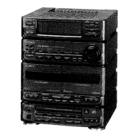
Identification of various model versions and their power voltage specifications.

SECTION 2 GENERAL

Main Unit Controls Overview

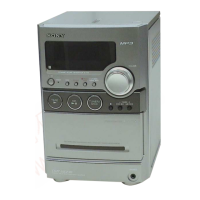
Listing of controls and features on the main unit with corresponding numbers.

Main Unit Button Descriptions

Descriptions of various buttons and their functions on the main unit.

Remote Control Operations

Remote Control Button Functions

Descriptions of various buttons on the remote control.

SECTION 3 DISASSEMBLY

Disassembly Flowchart

Flowchart illustrating the disassembly sequence of the set.

Cabinet Disassembly Steps

Component Disassembly

Board and Unit Removal

SECTION 4 TEST MODE

SECTION 5 MECHANICAL ADJUSTMENTS

SECTION 6 ELECTRICAL ADJUSTMENTS

CD Section Adjustments

SECTION 7 DIAGRAMS

Main System Block Diagram

CD Board Printed Wiring Layouts

CD Board Schematic Diagram

Main Board Layout and Components

Main Board Printed Wiring Layout

Printed wiring board layout for the main board.

Main Board Schematic Diagram (Part 1)

Main Board Schematic Diagram (Part 2)

Panel Board Layout and Components

Panel Board Printed Wiring Layout

Printed wiring board layout for the panel board.

Panel Board Schematic Diagram

DC Board Layout and Components

DC Board Printed Wiring Layout

Printed wiring board layout for the DC board.

AC Board Layout and Components

AC Board Printed Wiring Layout

Printed wiring board layout for the AC board.

Power Supply Section Schematic Diagram

SECTION 4 DIAGRAMS

IC Pin Function Descriptions

IC Pin Function Descriptions (Panel Board)

System Controller IC Pinout (Panel Board)

5. EXPLODED VIEW

Mechanical Deck Exploded View

Panel Board Exploded View

Top Cabinet Section Exploded View

Main Board Exploded View

AC and DC Board Exploded View

6. ELECTRICAL PARTS LIST

SUPPLEMENT-1: Specification Changes

New vs. Former Type Discrimination

Information on distinguishing between new and former types.

1. NEW/FORMER TYPE DISCRIMINATION

2. DISASSEMBLY

Disassembly Flow and Cabinet Removal

Flowchart and procedure for disassembling the main cabinet.

3. ELECTRICAL ADJUSTMENTS

4. DIAGRAMS

CD Servo System Block Diagram

Block diagram illustrating the CD servo system architecture.

IC Pin Function Descriptions (CD DSP)

IC Pin Function Descriptions (System Controller)

REVISION HISTORY

Related product manuals