EasyManua.ls Logo

Sony HCD-NEZ30 User Manual

Sony HCD-NEZ30
74 pages
To Next Page IconTo Next Page
Page #1 background imageLoading...
Page #1 background image
SERVICE MANUAL
COMPACT DISC DECK RECEIVER
HCD-NEZ30
Ver. 1.5 2007.04
SPECIFICATIONS
9-887-030-06
2007D05-1
© 2007.04
Sony Corporation
Personal Audio Division
Published by Sony Techno Create Corporation
US Model
Canadian Model
UK Model
E Model
East European Model
HCD-NEZ30 is the amplifier, CD player, tape deck
and tuner section in CMT-NEZ30.
Model Name Using Similar Mechanism HCD-NEZ3
CD Section Base Unit Name BU-K8BD83S-WOD
Optical Pick-up block Name KSM-213CDP
TAPE Section
Model Name Using Similar Mechanism NEW
Tape Transport Mechanism Type CMAL5Z235A
AUDIO POWER SPECIFICATIONS
POWER OUTPUT AND TOTAL HARMONIC DISTORTION:
( The United States model only)
With 6 ohm loads, both channels driven, from 120 – 10,000 Hz; rated 15 watts
per channel minimum RMS power, with no more than 10% total harmonic
distortion from 250 milliwatts to rated output.
Amplifier section
North-American model:
Continuous RMS power output (reference): 15 + 15 W (6 ohms at 1 kHz,
10% THD)
European model:
DIN power output (rated): 11 + 11 W (6 ohms at 1 kHz, DIN)
Continuous RMS power output (reference): 17 + 17 W (6 ohms at 1 kHz,
10% THD)
Music power output (reference): 28 + 28 W
The following are measured at AC 220 V, 50/60 Hz (Argentine model), AC
120 V, 60 Hz (Mexican model), AC 120, 220 or 230 – 240 V, 50/60 Hz (other
models)
DIN power output (rated): 11 + 11 W (6 ohms at 1 kHz, DIN)
Continuous RMS power output (reference): 15 + 15 W (6 ohms at 1 kHz,
10% THD)
Inputs
AUDIO IN: Sensitivity 250 mV, impedance 47 kilohms
Outputs
PHONES: Accepts headphones with an impedance of 8 ohms or more
SPEAKER: Accepts impedance of 6 to 16 ohms
CD player section
System: Compact disc and digital audio system
Laser Diode Properties
Emission Duration: Continuous
Laser Output*: Less than 44.6µW
* This output is the value measurement at a distance of 200 mm from the
objective lens surface on the Optical Pick-up Block with 7mm aperture.
Tape deck section
Recording system: 4-track 2-channel, stereo
AM tuner section:
Tuning range
Pan-American model: 530 – 1,710 kHz (with 10 kHz tuning interval)
531 – 1,710 kHz (with 9 kHz tuning interval)
Other models: 530 – 1,710 kHz (with 10 kHz tuning interval)
European models: 531 – 1,602 kHz (with 9 kHz tuning interval)
531 – 1,602 kHz (with 9 kHz tuning interval)
Antenna: AM loop antenna, external antenna terminal
Intermediate frequency: 450 kHz
General
Power requirements
North American model: AC 120 V, 60 Hz
Mexican model: AC 120 V, 60 Hz
European model: AC 230 V, 50/60 Hz
Argentine model: AC 220 V, 50/60 Hz
Other models: AC 120, 220 or 230 – 240 V, 50/60 Hz
Adjustable with voltage selector
Power consumption:
North American model: 45 watts
Other models: 45 watts
Dimensions (w/h/d) (excl. speakers):
Mass (excl. speakers):
North
Approx. 164 × 235 × 265 mm
American model: Approx. 3.2 kg
European model: Approx. 3.6 kg
Other models: Approx. 3.3 kg
Design and specifications are subject to change without notice.
Tuner section
FM stereo, FM/AM superheterodyne tuner
FM tuner section:
Tuning range
North American model: 87.5 – 108.0 MHz (100 kHz step)
Other models: 87.5 – 108.0 MHz (50 kHz step)
Antenna: FM lead antenna
Antenna terminals: 75 ohms unbalanced
Intermediate frequency: 10.7 MHz
w
w
w
.
x
i
a
o
y
u
1
6
3
.
c
o
m
Q
Q
3
7
6
3
1
5
1
5
0
9
9
2
8
9
4
2
9
8
T
E
L
1
3
9
4
2
2
9
6
5
1
3
9
9
2
8
9
4
2
9
8
0
5
1
5
1
3
6
7
3
Q
Q
TEL 13942296513 QQ 376315150 892498299
http://www.xiaoyu163.com
Question and Answer IconNeed help?

Do you have a question about the Sony HCD-NEZ30 and is the answer not in the manual?

Sony HCD-NEZ30 Specifications

General IconGeneral
BrandSony
ModelHCD-NEZ30
CategoryCar Receiver
LanguageEnglish

Summary

SERVICING NOTES

Handling the Optical Pick-Up Block or Base Unit

Instructions for safely handling the optical pick-up block and base unit during repair.

Laser Diode Emission Check

Procedure for checking laser diode emission, emphasizing safe observation distance.

Unleaded Solder Usage

Guidelines for using unleaded solder, including characteristics and precautions.

GENERAL

Basic Operations

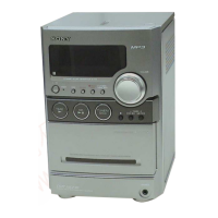
Overview of fundamental controls for playing CDs, tapes, and tuning radios.

System Usage Before First Use

Instructions for initial setup, including remote control battery insertion and clock setting.

Additional Operations

Procedures for creating custom CD programs, recording tapes, and using timers.

DISASSEMBLY

Disassembly Flow

Step-by-step guide showing the order of disassembly for the entire unit.

Cabinet Disassembly

Instructions on how to remove and disassemble the main cabinet.

Base Unit Disassembly

Guide for disassembling the base unit, including the optical pick-up block.

Front Panel Disassembly

Procedures for removing and disassembling the front panel section.

Mechanical Deck Disassembly

Steps to remove and disassemble the tape mechanical deck.

Main Board and Tuner Disassembly

Instructions for removing the main board and the FM/AM tuner section.

TEST MODE

Cold Reset Procedure

How to perform a cold reset to clear all stored data and reset the system.

Panel Test Mode

Procedure to test all segments of the liquid crystal display and view system information.

CD Error History Display

How to access and interpret the CD error history codes displayed on the unit.

MECHANICAL ADJUSTMENTS

Precautions for Mechanical Adjustments

Important notes and precautions before performing mechanical adjustments.

Torque and Tape Tension Measurements

Specifications and procedures for measuring torque and tape tension.

ELECTRICAL ADJUSTMENTS

Record/Playback Head Azimuth Adjustment

Procedure for adjusting the azimuth of the record/playback head for optimal audio quality.

DIAGRAMS

CD Servo Section Block Diagram

A block diagram illustrating the signal flow and components in the CD servo section.

Main Section Block Diagram

A block diagram showing the signal paths and interconnections of the main unit components.

Printed Wiring Boards and Schematic Diagrams

Contains printed wiring boards and schematic diagrams for various sections like CD, Main, Panel, DC, AC, and Power Supply.

EXPLODED VIEWS

Cabinet Section Exploded View

Exploded view of the cabinet, showing all external and internal parts.

Mechanical Deck Section Exploded View

Exploded view of the tape mechanical deck assembly with part numbers.

Panel Board Section Exploded View

Exploded view of the front panel board and associated components.

Cabinet (Top) Section Exploded View

Exploded view of the top cabinet section, showing internal components.

Main Board Section Exploded View

Exploded view of the main board and related power cords.

AC/DC Board Section Exploded View

Exploded view of the AC and DC power supply boards.

ELECTRICAL PARTS LIST

Capacitors and Connectors

List of capacitors and connectors with part numbers, descriptions, and specifications.

Diodes and Filters

List of diodes and line filters with part numbers and descriptions.

Resistors and Relays

List of resistors and relays with part numbers and descriptions.

Transformers and Semiconductor Devices

List of transformers, semiconductor devices, and their part numbers.

REVISION HISTORY

Service Manual Revision Log

Records changes made to the service manual across different versions, including dates and descriptions.

SUPPLEMENT-1 NEW/FORMER DESCRIPTION

CD Board Component Side Details

Details on the CD board component side, showing former and new part numbers.

MAIN Board Component Side Details

Details on the MAIN board component side, showing former and new part numbers.

Circuit Boards Location Diagram

Diagram showing the physical location of the CD and MAIN boards within the unit.

SUPPLEMENT-2 NEW/FORMER DESCRIPTION

HEAD PHONE Board Component Side Details

Details on the HEAD PHONE board component side, showing former and new part numbers.

Circuit Boards Location Diagram

Diagram showing the physical location of the HEAD PHONE board within the unit.

SUPPLEMENT-3 NEW/FORMER DESCRIPTION

PANEL Board Component Side Details

Details on the PANEL board component side, showing former and new part numbers.

Circuit Boards Location Diagram

Diagram showing the physical location of the PANEL board within the unit.

Related product manuals