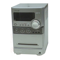
Do you have a question about the Sony HCD-NEZ30 and is the answer not in the manual?
| Brand | Sony |
|---|---|
| Model | HCD-NEZ30 |
| Category | Car Receiver |
| Language | English |
Instructions for safely handling the optical pick-up block and base unit during repair.
Procedure for checking laser diode emission, emphasizing safe observation distance.
Guidelines for using unleaded solder, including characteristics and precautions.
Overview of fundamental controls for playing CDs, tapes, and tuning radios.
Instructions for initial setup, including remote control battery insertion and clock setting.
Procedures for creating custom CD programs, recording tapes, and using timers.
Step-by-step guide showing the order of disassembly for the entire unit.
Instructions on how to remove and disassemble the main cabinet.
Guide for disassembling the base unit, including the optical pick-up block.
Procedures for removing and disassembling the front panel section.
Steps to remove and disassemble the tape mechanical deck.
Instructions for removing the main board and the FM/AM tuner section.
How to perform a cold reset to clear all stored data and reset the system.
Procedure to test all segments of the liquid crystal display and view system information.
How to access and interpret the CD error history codes displayed on the unit.
Important notes and precautions before performing mechanical adjustments.
Specifications and procedures for measuring torque and tape tension.
Procedure for adjusting the azimuth of the record/playback head for optimal audio quality.
A block diagram illustrating the signal flow and components in the CD servo section.
A block diagram showing the signal paths and interconnections of the main unit components.
Contains printed wiring boards and schematic diagrams for various sections like CD, Main, Panel, DC, AC, and Power Supply.
Exploded view of the cabinet, showing all external and internal parts.
Exploded view of the tape mechanical deck assembly with part numbers.
Exploded view of the front panel board and associated components.
Exploded view of the top cabinet section, showing internal components.
Exploded view of the main board and related power cords.
Exploded view of the AC and DC power supply boards.
List of capacitors and connectors with part numbers, descriptions, and specifications.
List of diodes and line filters with part numbers and descriptions.
List of resistors and relays with part numbers and descriptions.
List of transformers, semiconductor devices, and their part numbers.
Records changes made to the service manual across different versions, including dates and descriptions.
Details on the CD board component side, showing former and new part numbers.
Details on the MAIN board component side, showing former and new part numbers.
Diagram showing the physical location of the CD and MAIN boards within the unit.
Details on the HEAD PHONE board component side, showing former and new part numbers.
Diagram showing the physical location of the HEAD PHONE board within the unit.
Details on the PANEL board component side, showing former and new part numbers.
Diagram showing the physical location of the PANEL board within the unit.
 Loading...