SERVICE MANUAL
Sony Corporation
Published by Sony Techno Create Corporation
HCD-EX6/EX6T/EX8/
EX8T/EX9/EX9T
9-889-803-02
2010L04-1
©
2010.12
E Model
Ver. 1.1 2010.12
• HCD-EX6 is the amplifi er, USB, CD player
and tuner section in MHC-EX6.
• HCD-EX6T is the amplifi er, USB, CD player,
tape deck and tuner section in MHC-EX6T.
• HCD-EX8 is the amplifi er, USB, CD player
and tuner section in MHC-EX8.
• HCD-EX8T is the amplifi er, USB, CD player,
tape deck and tuner section in MHC-EX8T.
• HCD-EX9 is the amplifi er, USB, CD player
and tuner section in MHC-EX9.
• HCD-EX9T is the amplifi er, USB, CD player,
tape deck and tuner section in MHC-EX9T.
HCD-EX6/EX8/EX9
COMPACT DISC RECEIVER
HCD-EX6T/EX8T/EX9T
COMPACT DISC DECK RECEIVER
CD Section
Model Name Using Similar Mechanism New
Mechanism Type CDM88CL-D1BD74UR
Optical Pick-up Block Name DA11MMVGP
Tape Deck Section
(HCD-EX6T/EX8T/EX9T)
Model Name Using Similar Mechanism HCD-EC69T/EC79T/EC99T
Tape Transport Mechanism Type TCM-J1 or CS-21SC-901TP
SPECIFICATIONS
Amplifi er section
The following measured at AC 127 V,
60 Hz (Mexican model)
The following measured at AC 220 V,
50/60 Hz (Argentine model)
The following measured at AC 120 V,
220 V, 240 V, 50/60 Hz (Other models)
HCD-EX9/EX9T
Front Speaker:
Power output (rated):
Low channel
40 W + 40 W (at 8 Ω, 1 kHz, 1%
THD)
High channel
40 W + 40 W (at 8 Ω, 1 kHz, 1%
THD)
RMS output power (reference):
Low channel
85 W + 85 W (per channel at 8 Ω,
1 kHz)
High channel
85 W + 85 W (per channel at 8 Ω,
1 kHz)
Subwoofer:
RMS output power (reference):
125 W (at 4 Ω, 80 Hz)
HCD-EX8/EX8T
Power output (rated):
Low channel
50 W + 50 W (at 8 Ω, 1 kHz, 1%
THD)
High channel
50 W + 50 W (at 8 Ω, 1 kHz, 1%
THD)
RMS output power (reference):
Low channel
100 W + 100 W (per channel at 8 Ω,
1 kHz)
High channel
100 W + 100 W (per channel at 8 Ω,
1 kHz)
HCD-EX6/EX6T
Power output (rated):
40 W + 40 W (at 6 Ω, 1 kHz, 1%
THD)
RMS output power (reference):
90 W + 90 W (per channel at 6 Ω,
1 kHz)
Inputs
PC IN (stereo mini jack):
Sensitivity 800 mV, impedance
22 kilohms
Outputs
PHONES (stereo mini jack):
accepts headphones with an
impedance of 8 Ω or more
SPEAKERS: impedance
HCD-EX9/EX9T/EX8/EX8T: 8 Ω
HCD-EX6/EX6T: 6 Ω
SUBWOOFER (HCD-EX9/EX9T only):
impedance 4 Ω
USB section
Supported bit rate:
MP3 (MPEG 1 Audio Layer-3):
32 kbps – 320 kbps, VBR
WMA: 48 kbps – 192 kbps
AAC: 48 kbps – 320 kbps
Sampling frequencies:
MP3 (MPEG 1 Audio Layer-3):
32/44.1/48 kHz
WMA: 44.1 kHz
AAC: 44.1 kHz
(USB) port:
Maximum current:
500 mA
CD player section
System:
Compact disc and digital audio
system
Laser Diode Properties
Emission Duration: Continuous
Laser Output*: Less than 44.6μW
* This output is the value
measurement at a distance of
200mm from the objective lens
surface on the Optical Pick-up
Block with 7mm aperture.
Frequency response: 20 Hz – 20 kHz
Signal-to-noise ratio: More than 90 dB
Dynamic range: More than 88 dB
Tape deck section (HCD-EX9T/
EX8T/EX6T only)
Recording system: 4-track 2-channel, stereo
Tuner section
FM stereo, FM/AM superheterodyne tuner
Antenna:
FM lead antenna
AM loop antenna
FM tuner section:
Tuning range:
87.5 MHz ‒ 108.0 MHz (50 kHz step)
Intermediate frequency: 225 kHz
AM tuner section:
Tuning range
Latin American models:
530 kHz ‒ 1,710 kHz (10 kHz step)
531 kHz ‒ 1,710 kHz (9 kHz step)
Other models:
531 kHz ‒ 1,602 kHz (9 kHz step)
530 kHz ‒ 1,610 kHz (10 kHz step)
Intermediate frequency: 53 kHz
– Continued on next page –
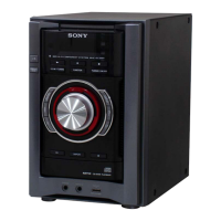
Photo: HCD-EX9T
• MPEG Layer-3 audio coding technology and pat-
ents licensed from Fraunhofer IIS and Thomson.
• Windows Media is a registered trademark of
Microsoft Corporation in the United States and/or
other countries.