Do you have a question about the Sony HCD-EC79 and is the answer not in the manual?
Details power output ratings and RMS output power for different models.
Lists supported bit rates and sampling frequencies for USB playback.
Provides laser diode properties, frequency response, S/N ratio, and dynamic range.
Details FM and AM tuning ranges and intermediate frequencies.
Covers power requirements, consumption, dimensions, and mass.
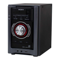
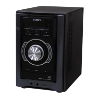
Identifies and describes the buttons and ports on the main unit.
Precautions for handling the optical pick-up block to prevent electrostatic damage.
Safety guidelines for checking the laser diode emission to avoid eye exposure.
Details properties of unleaded solder and precautions during soldering.
Procedure to unlock the disc tray for anti-theft demonstration discs.
Outlines the step-by-step procedure for disassembling the unit.
Instructions for removing the left and right side panels of the unit.
Steps for removing the top panel from the unit.
Procedure for removing the main circuit board from the unit.
Steps to remove the front panel assembly, including CD tray operation.
Instructions for disassembling the back panel section of the unit.
Procedure for removing the CD mechanism module from the unit.
Steps for removing the base unit assembly, including springs and insulators.
Procedure for disassembling the optical pick-up base assembly.
Instructions for replacing the belt in the CD mechanism, including screw and cover removal.
Clears all data and returns the unit to initial conditions.
Activates LEDs and LCD segments for panel testing.
Enables unlimited CD playback repeats.
For antitheft, locks or unlocks the CD tray.
Controls the CD power supply on/off state, retained even when unplugged.
Switches between 9 kHz and 10 kHz AM tuning intervals.
Allows optional movement of the CD sled motor for cleaning.
Combines CD ship mode with a cold reset procedure.
Checks optical pick-up system servo operations, including S-Curve, RAM Read/Write, Command Out, and Error Rate modes.
Moves the SLED and controls optical pick-up laser power on/off.
Displays past CDM and BD mechanism errors for troubleshooting.
Allows access to factory settings for S character, Tracking servo, and RF gain.
Checks the focus bias by verifying the eye pattern waveform.
Covers AM and FM frequency coverage and tracking adjustments.
Verifies AM frequency display against digital voltmeter readings.
Adjusts for maximum reading on the level meter for AM tracking.
Adjusts FM frequency coverage using a digital voltmeter.
Adjusts for a minimum reading on the level meter for FM tracking.
Adjusts the FM detector for optimal modulation distortion.
Verifies automatic scanning stops correctly when FM signals are received.
Illustrates the signal flow for CD and Tuner functions.
Shows the signal paths for the main processing and output stages.
Depicts the power supply and front panel control signal connections.
Detailed circuit diagram for the CD processing board.
Circuit diagram for the USB controller and interface.
Part two of the main circuit board schematic, detailing tuner and audio sections.
Layouts for the 2CH-4CH and 3CH amplifier boards.
Circuit diagram for the 3-channel amplifier board specific to EC99 models.
Circuit diagram for the front panel control and display interface.
Circuit diagrams for audio, key, and power supply interface boards.
Block diagrams for key ICs on the CD board.
Block diagrams for key ICs on the main board.
Detailed pinout and function description for the CD-MP3 processor IC.
Exploded diagram showing chassis, front panel, and side panels.
Detailed exploded view of the front panel components and assembly.
Exploded view illustrating chassis components, power cord, and fan.
Exploded view of the main section, showing board placements and transformers.
Exploded view of the CD mechanism, including motors, springs, and belts.
Component list for the 2-channel and 4-channel amplifier board.
Component list for the 3-channel amplifier board.
Component lists for the 3CH AMP and CD boards.
Component lists for the CD, JACK, and KEY interface boards.
Component lists for PANEL, PT-SWITCH, and REG boards.
Component lists for PT-SINGLE and REG boards.
Component list for the MAIN board, covering diodes, coils, transistors, filters, and ICs.
Component list for the MAIN board, focusing on resistors.
Component list for the MAIN board, continuing resistor listings.
Component lists for MAIN and PANEL boards, including relays, transformers, and capacitors.
Component lists for the PANEL board, covering resistors, diodes, ICs, and transistors.
Component lists for PANEL and PT-SINGLE boards, including resistors, switches, vibrator, and capacitors.
Component lists for PT-SWITCH, REG, and USB boards.
Lists miscellaneous cables, transformers, fans, switches, and accessories.
| Category | Car Receiver |
|---|---|
| Brand | Sony |
| Model | HCD-EC79 |
| CD Player | Yes |
| USB Port | Yes |
| AM/FM Tuner | Yes |
| Remote Control | Yes |