Do you have a question about the Sony HCD-H61 and is the answer not in the manual?
Details output power and total harmonic distortion for various models.
Specifications for the CD player, including frequency response and impedance.
Specifications for the tape deck, including frequency response and wow/flutter.
Details antenna impedance and amplifier power output.
Details on power requirements and consumption based on destination.
Procedures for safety checks, leakage tests, and component warnings.
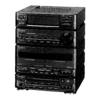
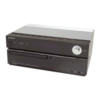
Details on model identification and specifications.
Checks for laser diode operation, focus search, and handling precautions.
Instructions on how to open the disc tray manually when the unit is off.
Identification of parts, clock setting, remote functions, and basic CD/Amp operations.
Adjusting audio, playing CDs, selecting tracks, and cassette playback.
CD programming, radio tuning, tape playback, and recording procedures.
Using equalizer, tone controls, time-activated operation, and singing along features.
Procedure for removing the outer case from the HCD-H61M model.
Instructions for removing the power block and main circuit board.
Procedures for removing CD and TC mechanism assemblies.
General precautions before performing mechanical adjustments.
Table listing torque values for various screws and components.
Procedures for adjusting tape speed and playback level.
Procedures for adjusting record bias and record level.
Adjustments for the deck section, including playback and record levels.
Electrical adjustments for FM, AM, and SW tuner sections.
Diagrams showing the physical location of circuit boards within the unit.
Visual representations of semiconductor pin configurations and lead arrangements.
Block diagrams illustrating the internal functions of various integrated circuits.
Exploded view of the case and power supply components.
Exploded view of the front panel assembly and its parts.
Exploded view of the mechanism deck chassis and associated parts.
Exploded views of the mechanism deck assembly sections.
Exploded views of the CD mechanism assembly sections.
Lists of capacitors and diodes with their specifications.
Lists of resistors and transistors with their specifications.
Lists of connectors, switches, indicators, and lamps.
Details differences in the MD board (B Deck) between models TCM-190RB43A and TCM-190RB43.
Lists parts for optical devices KSS-240A and KSS-390A, noting differences.
Information on circuit changes made to various boards, affecting diagrams and parts lists.
| Brand | Sony |
|---|---|
| Model | HCD-H61 |
| Category | Car Receiver |
| Language | English |