Do you have a question about the Sony HCD-SPZ50 and is the answer not in the manual?
Details amplifier, CD, tape deck, and tuner specifications for HCD-SPZ50/SPZ70 models.
Precautions for optical pick-up, laser diode, solder, model ID, and antitheft lock.
Instructions for replacing boards, ICs, and C25, including discrimination and combination details.
Procedures for Cold Reset, Test Modes, Antitheft Lock, and CD Power Management.
Guidelines for mechanical adjustments, torque, tape tension measurements, and necessary precautions.
Procedures for electrical adjustments, including deck section and head azimuth alignment.
Block diagrams illustrating the CD servo and main sections of the system.
Block diagrams for the amplifier, panel, and power supply sections.
Explains symbols and conventions for printed wiring boards and schematic diagrams.
Visual guide showing the physical location of all circuit boards within the unit.
Printed wiring board and schematic diagrams for the CD board.
Printed wiring board and schematic diagrams for the TC (Tape Control) board.
Printed wiring board layout for the MAIN board, showing component placement.
Schematic diagram for the MAIN board (part 1/3), focusing on the system controller IC1301.
Printed wiring board and schematic diagrams for the AMP board (SPZ70).
Printed wiring board layout for the PANEL board (part 1/2).
Printed wiring board and schematic diagrams for the POWER board.
Displays characteristic waveforms for CD, TC, Main, and FL board components.
Block diagrams for key ICs like IC203 (BH18LB1WG-TR) and IC402 (BA5947FM-E2).
Detailed pinout description for IC201 (CXD3014A-201R) on the CD board.
Detailed pin description for IC1301 (System Controller) on the MAIN board, covering pins 1-43.
Detailed pin description for IC11 on the POWER board, listing pin names, I/O, and functions.
Exploded views of unit assemblies, front panel, CD, Power, FL, and TC sections with part identification.
Comprehensive list of capacitors, resistors, and semiconductors used in the unit.
List of specific circuit boards (AMP, CD, FL, HP, MAIN, POWER, TC) and connectors.
Guide to differentiate between new and former HP A-IN and MAIN boards by part number.
Printed wiring board layout for the MAIN board, showing component placement and connector locations.
Schematic diagram for the MAIN board (part 3/3), detailing motor drives and power supply connections.
Printed wiring board layout for the HP A-IN board, showing component placement.
List of capacitors, resistors, and semiconductors for HP A-IN and MAIN boards.
List of connectors and switches for HP A-IN and MAIN boards.
Log of revisions to the service manual, detailing dates and changes made in each version.
| Brand | Sony |
|---|---|
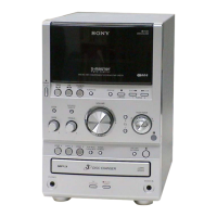
| Model | HCD-SPZ50 |
| Category | Car Receiver |
| Language | English |