Do you have a question about the Sony STR-414L and is the answer not in the manual?
Details power requirements, consumption, dimensions, and weight of the receiver.
Details FM frequency range, antenna, intermediate frequency, and sensitivity.
Lists usable sensitivity, S/N ratio, harmonic/IM distortion, separation, and frequency response.
Explains automatic FM/LW band switching via optical detection and program sensor.
Steps for removing the top cover of the unit.
Procedure to remove the front glass assembly.
Instructions for detaching the bottom plate.
Guide for removing the front panel components.
First part of the procedure for replacing power transistors.
Second part of the procedure for power transistor replacement.
Initial steps for dial cord stringing.
The process of stringing the dial cord.
Steps for installing the dial pointer.
Procedure for adjusting the DC bias of the unit.
Adjusting the MW frequency coverage.
Adjusting the MW tracking.
Adjusting the SW frequency coverage.
Adjusting the SW tracking.
Adjusting the LW external antenna coil.
Adjusting the LW tracking.
Adjusting the LW frequency coverage.
Adjusting the FM frequency coverage.
Adjusting the FM tracking.
Procedures for aligning the FM discriminator (Primary and Secondary sides).
Procedure for adjusting the FM stereo separation.
Alignment of the FM IF stage and MPX section.
Procedure for the primary side FM discriminator alignment.
Alignment of the FM IF stage.
Procedures for MPX adjustment (Regular and Simple methods).
Diagram showing component mounting on conductor and component sides.
List of semiconductor components with part numbers.
List of coils with part numbers.
List of transformers and filters with part numbers.
List of capacitors with part numbers and values.
List of resistors with part numbers and values.
Listing of various jacks and connectors.
Listing of miscellaneous parts like cords and fuses.
Table of 1/4 watt carbon resistors.
Continuation of resistor listings.
List of switches with part numbers.
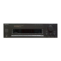
| Type | Stereo Receiver |
|---|---|
| Power Output | 20 watts per channel into 8Ω (stereo) |
| Dimensions | 430 x 280 x 100 mm |
| Weight | 6.5 kg |
| Frequency response | 20 Hz - 20 kHz |
| Total harmonic distortion | < 0.1% |
| Input sensitivity | 2.5 mV (Phono), 150 mV (Line) |
| Speaker load impedance | 8 ohms |
| Tuning Range | FM, AM |
| Inputs | Phono, Aux |
| Outputs | Speaker |
| Signal to noise ratio | > 70 dB |
| Signal-to-Noise Ratio | > 70 dB |