Do you have a question about the Sony STR-S5L and is the answer not in the manual?
Details power output, bandwidth, distortion, inputs, and outputs.
Covers FM/AM tuning ranges, intermediate frequency, sensitivity, and selectivity.
Includes system type, power requirements, consumption, dimensions, and weight.
Details safe storage and handling procedures for MOS ICs and soldering irons.
Explains methods for handling and checking C-MOS ICs to prevent damage.
Explains the sound enhancer circuit's function and resonance characteristics.
Describes collector follower output, protector, and legato linear circuits.
Lists and describes the functions of IC303 and IC305 terminals.
Illustrates the integrated circuit connections and surrounding components.
Provides a high-level functional overview of the receiver's main blocks.
Presents various detailed schematic diagrams of the unit's circuits.
Covers FM IF offset, discriminator, and VCO adjustments for optimal tuning.
Covers AM IF offset and S-curve adjustments for accurate AM reception.
Details calibration of the LED level meter and bias settings for amplifier stages.
Shows lead configurations and pinouts for various semiconductors.
Illustrates mounting positions for components and circuit boards.
Provides visual exploded views of the unit's assembly for disassembly.
Lists all part numbers, descriptions, and quantities for unit components.
Covers removal of top cover, heat sink, and equalizer board.
Details front panel, motor chassis, and control board removal.
Instructions for removing bottom plate, sub-panels, and circuit board brackets.
Covers removal of display, function, level meter, and speaker boards.
| Brand | Sony |
|---|---|
| Model | STR-S5L |
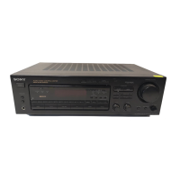
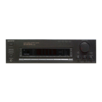
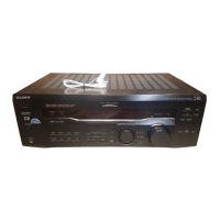
| Category | Stereo Receiver |
| Language | English |