EasyManua.ls Logo

Sony STR-DB1070 - Fm Stereo/fm-am Receiver User Manual

Sony STR-DB1070 - Fm Stereo/fm-am Receiver
86 pages
To Next Page IconTo Next Page
Page #1 background imageLoading...
Page #1 background image
SERVICE MANUAL
FM STEREO/FM-AM RECEIVER
SPECIFICATIONS
STR-DB870/DB1070
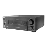
Photo: STR-DB870
Ver 1.0 2001.04
9-873-842-11 Sony Corporation
2001D0500-1 Home Audio Company
C 2000.4 Shinagawa Tec Service Manual Production Group
US Model
E Model
Chinese Model
STR-DB1070
Canadian Model
AEP Model
UK Model
STR-DB870/DB1070
– Continued on next page –
This receiver incorporates Dolby* Digital and Pro Logic Surround
and the DTS** Digital Surround System.
* Manufactured under license from Dolby Laboratories.
“Dolby”, “Pro Logic” and the double-D symbol are trademarks
of Dolby Laboratories.
**“DTS” and “DTS Digital Surround” are registered trademarks
of Digital Theater Systems, Inc.
AUDIO POWER SPECIFICATIONS
POWER OUTPUT AND TOTAL
HARMONIC DISTORTION:
With 8 ohm loads, both channels driven, from
20 20,000 Hz; rated 100 watts per channel
minimum RMS power, with no more than
0.09 % total harmonic distortion from 250
milliwatts to rated output (Models of area code
U only).
Amplifier section
POWER OUTPUT
Models of area code U, CA
Rated Power Output at Stereo Mode
(8 ohms 20 Hz 20 kHz, THD 0.09 %)
100 W + 100 W
(4 ohms 20 Hz 20 kHz, THD 0.09 %)
90 W + 90 W
Reference Power Output
(8 ohms 20 Hz 20 kHz, THD 0.09 %)
STR-DB1070: FRONT
1)
:100 W + 100 W
CENTER
1)
: 100 W
SURR
1)
: 100 W + 100 W
SURR BACK
1)
: 100 W
STR-DB870: FRONT
1)
: 100 W + 100 W
CENTER
1)
: 100 W
SURR
1)
: 100 W + 100 W
(4 ohms 20 Hz 20 kHz, THD 0.09 %)
STR-DB1070: FRONT:
1)
90 W + 90 W
CENTER
1)
: 90 W
SURR
1)
: 90 W + 90 W
SURR BACK
1)
: 90 W
STR-DB870: FRONT
1)
:90 W + 90 W
CENTER
1)
: 90 W
SURR
1)
: 90 W + 90 W
Models of other area code
Rated Power Output at Stereo Mode
(8 ohms 1 kHz, THD 0.7 %)
STR-DB1070: 100 W + 100 W
2)
90 W + 90 W
3)
STR-DB870: 100 W + 100 W
2)
(4 ohms 1 kHz, THD 0.7 %)
STR-DB1070: 90 W + 90 W
2)
80 W + 80 W
3)
STR-DB870: 100 W + 100 W
2)
Reference Power Output
2)
(8 ohms 1 kHz, THD 0.7 %)
STR-DB1070: FRONT
1)
: 100 W + 100 W
CENTER
1)
: 100 W
SURR
1)
: 100 W + 100 W
SURR BACK
1)
: 100 W
STR-DB870: FRONT
1)
: 100 W + 100 W
CENTER
1)
: 100 W
SURR
1)
: 100 W + 100 W
(4 ohms 1 kHz, THD 0.7 %)
STR-DB1070: FRONT
1)
: 90 W + 90 W
CENTER
1)
: 90 W
SURR
1)
: 90 W + 90 W
SURR BACK
1)
: 90 W
STR-DB870: FRONT
1)
: 100 W + 100 W
CENTER
1)
: 100 W
SURR
1)
: 100 W + 100 W
(8 ohms 20 Hz 20 kHz, THD 0.09 %)
STR-DB1070: FRONT
1)
: 90 W + 90 W
CENTER
1)
: 90 W
SURR
1)
: 90 W + 90 W
SURR BACK
1)
: 90 W
STR-DB870: FRONT
1)
: 90 W + 90 W
CENTER
1)
: 90 W
SURR
1)
: 90 W + 90 W
(4 ohms 20 Hz 20 kHz, THD 0.09 %)
STR-DB1070: FRONT
1)
: 80 W + 80 W
CENTER
1)
: 80 W
SURR
1)
: 80 W + 80 W
SURR BACK
1)
: 80 W
STR-DB870: FRONT
1)
: 90 W + 90 W
CENTER
1)
: 90 W
SURR
1)
: 90 W + 90 W
1) Depending on the sound field settings and the
source, there may be no sound output.
2) Measured under the following conditions:
Area code Power requirements
E 240 V AC, 50 Hz
CN, SP, CEL, KR 230 V AC, 50 Hz
TW 110 V AC, 60 Hz
3) Measured under the following conditions:
Area code Power requirements
CN 220 V AC, 50 Hz
Frequency response
PHONO
CD/SACD, TAPE,
MD/DAT, MD/TAPE,
TV/SAT, DVD/LD,
VIDEO 1, 2, 3
RIAA equalization curve
±0.5 dB
10 Hz 100 kHz
±3 dB (with sound field,
equalizer, and bass boost
bypassed)

Other manuals for Sony STR-DB1070 - Fm Stereo/fm-am Receiver

Question and Answer IconNeed help?

Do you have a question about the Sony STR-DB1070 - Fm Stereo/fm-am Receiver and is the answer not in the manual?

Sony STR-DB1070 - Fm Stereo/fm-am Receiver Specifications

General IconGeneral
BrandSony
ModelSTR-DB1070
Frequency Response10 Hz - 100 kHz
Digital InputsCoaxial, Optical
Video ConnectionsComposite, S-Video
Number of Channels5.1
TypeStereo Receiver
Tuning RangeFM, AM
Power Output100W per channel
OutputSpeaker
Speaker Load Impedance8 ohms
Dimensions430 x 157 x 380 mm
InputsCD, Tape
OutputsTape, Video

Summary

STR-DB870/DB1070 Service Manual

Specifications

Comprehensive technical details including power, audio, and general capabilities.

Safety Information

Component Replacement Notes

Guidelines for replacing chip components, especially tantalum capacitors.

Safety Checks and Leakage Test

Procedures for checking AC leakage and ensuring safe operation.

Servicing and General Information

Servicing Notes

General notes and procedures for service technicians.

General Overview

General information and model identification.

Disassembly Procedures

Disassembly Flow

A flowchart illustrating the sequence of disassembly steps.

Case and Board Removal

Instructions for removing the case, S-VIDEO, VIDEO, and Tuner boards.

VIDEO AU and DIGITAL Board Removal

Steps for removing the VIDEO AU and DIGITAL boards.

MAIN Board Removal

Detailed instructions for removing the MAIN board assembly.

Test Modes

Diagnostic and Test Modes

Procedures for various diagnostic and testing modes.

Diagram Information

Notes on Diagrams and Symbols

Explains conventions for printed wiring boards and schematic diagrams.

Circuit Board Locations

Schematic Diagrams

DIGITAL Board Schematics (1/5)

Part 1 of the schematic for the DIGITAL board.

DIGITAL Board Schematics (2/5)

Part 2 of the schematic for the DIGITAL board.

DIGITAL Board Schematics (3/5)

Part 3 of the schematic for the DIGITAL board.

DIGITAL Board Schematics (4/5)

Part 4 of the schematic for the DIGITAL board.

DIGITAL Board Schematics (5/5)

Part 5 of the schematic for the DIGITAL board.

VIDEO Board Schematics

Schematic diagram for the VIDEO board.

S-VIDEO/VIDEO AU Boards Schematics

Schematics for S-VIDEO and VIDEO AU boards.

MAIN Board Schematics (1/3)

Part 1 of the schematic for the MAIN board.

MAIN Board Schematics (2/3)

Part 2 of the schematic for the MAIN board.

MAIN Board Schematics (3/3)

Part 3 of the schematic for the MAIN board.

BIAS Board Schematics

Schematic diagram for the BIAS board.

DISP/SW Boards Schematics

Schematics for DISP and SW boards.

H.P/MUTING/POWER/SP/VIDEO 3 Boards Schematics

Schematics for auxiliary boards.

Power Supply Section Schematics

Schematics for power supply related boards.

Printed Wiring Boards

DIGITAL Board - Component Side Layout

Component layout for the DIGITAL board (component side view).

DIGITAL Board - Conductor Side Layout

Component layout for the DIGITAL board (conductor side view).

VIDEO Board Layout

Component layout for the VIDEO board.

S-VIDEO/VIDEO AU Boards Layouts

Component layouts for S-VIDEO and VIDEO AU boards.

MAIN Board Layout

Component layout for the MAIN board.

BIAS Board Layout

Component layout for the BIAS board.

DISP/SW Boards Layouts

Component layouts for DISP and SW boards.

H.P/MUTING/POWER/SP/VIDEO 3 Boards Layouts

Component layouts for auxiliary boards.

Power Supply Section Boards Layouts

Component layouts for power supply related boards.

IC Block Diagrams and Waveforms

IC Block Diagrams

Provides block diagrams for key ICs.

Waveforms

Example waveforms for DIGITAL and VIDEO boards.

IC Pin Function Descriptions

IC1101 PCM1800E/2K (DIGITAL Board)

Pinout and description for the PCM1800E/2K IC.

IC1201 PCM1604Y/2K (D/A CONVERTER)

Pinout and description for the PCM1604Y/2K IC.

IC1408 LC89056W-E (DIGITAL AUDIO INTERFACE RECEIVER)

Pinout and description for the LC89056W-E IC.

IC1408 LC89056W-E (DIGITAL AUDIO INTERFACE RECEIVER)

Pinout and description for the LC89056W-E IC.

IC1501 CDX9617R (AUDIO DSP1)

Pinout and description for the CDX9617R IC.

IC1601 CXD9616R (AUDIO DSP2)

Pinout and description for the CXD9616R IC.

IC1601 CXD9616R (AUDIO DSP2)

Pinout and description for the CXD9616R IC.

IC1601 CXD9616R (AUDIO DSP2)

Pinout and description for the CXD9616R IC.

IC1601 CXD9616R (AUDIO DSP2)

Pinout and description for the CXD9616R IC.

IC1601 CXD9616R (AUDIO DSP2)

Pinout and description for the CXD9616R IC.

IC1703 MB91154PMT2-G-102-E1 (SYSTEM CONTROLLER)

Pinout and description for the MB91154PMT2 IC.

IC1703 MB91154PMT2-G-102-E1 (SYSTEM CONTROLLER)

Pinout and description for the MB91154PMT2 IC.

IC1703 MB91154PMT2-G-102-E1 (SYSTEM CONTROLLER)

Pinout and description for the MB91154PMT2 IC.

IC1703 MB91154PMT2-G-102-E1 (SYSTEM CONTROLLER)

Pinout and description for the MB91154PMT2 IC.

IC307 MB90089F-G-238-BND (OSD DRIVER)

Pinout and description for the MB90089F-G-238-BND IC.

Exploded Views

Case Section Exploded View

Exploded view and parts list for the unit's case assembly.

Front Panel Sections Exploded View

Exploded views and parts lists for the front panel assembly (parts 1 & 2).

Chassis Sections Exploded View

Exploded views and parts lists for the chassis assembly (parts 1 & 2).

Electrical Parts List

Component Categories

Lists resistors, semiconductors, capacitors, connectors, diodes, fuses, transistors, relays, transformers.

BIAS, DC1, DC2, DIGITAL Board Components

Parts list details for BIAS, DC1, DC2, and DIGITAL boards.

BIAS Board Components

Parts list details for BIAS board resistors, capacitors, and vibrator.

BIAS/DC1/DC2 Board Components

Parts list details for BIAS/DC1/DC2 board components.

DC2 Board Components

Parts list details for DC2 board components.

DIGITAL Board Capacitors

Comprehensive capacitor list for the DIGITAL board.

DIGITAL Board Capacitors

Continuation of capacitor list for the DIGITAL board.

DIGITAL Board Ferrites, ICs, Connectors, Diodes

Parts list for ferrite beads, ICs, connectors, and diodes on the DIGITAL board.

DIGITAL Board ICs, Jacks, Shorts, Transistors, Resistors

Parts list for DIGITAL board ICs, jacks, shorts, transistors, and resistors.

DIGITAL Board Resistors

Further resistor list for the DIGITAL board.

DIGITAL/DISP Board Components

Parts list for DIGITAL and DISP boards.

DISP/H.P/MAIN Board Components

Parts list for DISP, H.P, and MAIN boards.

MAIN Board Capacitors

Comprehensive capacitor list for the MAIN board.

MAIN Board Capacitors

Continuation of capacitor list for the MAIN board.

MAIN Board Diodes, ICs, Jacks, Coils, Transistors

Parts list for diodes, ICs, jacks, coils, and transistors on the MAIN board.

MAIN Board Resistors

Continuation of resistor list for the MAIN board.

MAIN Board Resistors

Further resistor list for the MAIN board.

MAIN/MUTING/POWER Board Components

Parts list for MAIN, MUTING, and POWER boards.

S-VIDEO Board Components

Comprehensive parts list for the S-VIDEO board.

SP/SW Board Components

Parts list for SP and SW boards.

SW/VIDEO Board Components

Parts list for SW and VIDEO boards.

VIDEO Board Components

Parts list for VIDEO board components.

VIDEO Board Components

Continuation of parts list for the VIDEO board.

VIDEO 3/VIDEO AU/V.SWITCH Board Components

Parts list for VIDEO 3, VIDEO AU, and V.SWITCH boards.

Accessories and Manuals

Included Accessories and Manuals

List of included accessories and instruction manuals for various regions.
Revision History

Related product manuals