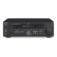
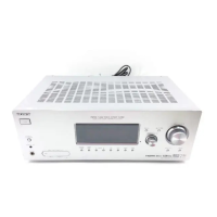
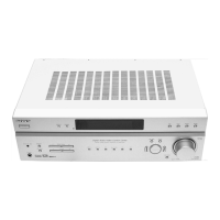
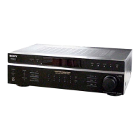
STR-DE475
US Model
Canadian Model
AEP Model
UK Model
Australian Model
Chinese Model
E Model
SERVICE MANUAL
FM STEREO FM-AM RECEIVER
Sony Corporation
Audio Entertainment Group
General Engineering Dept.
9-929-587-11
2001B1600-1
© 2001.2
— Continued on next page —
SPECIFICATIONS
Ver 1.0 2001. 02
Manufactured under license from Dolby Laboratories Licensing
Corporation.
“DOLBY” the double-D symbol ; “AC-3” and “Pro Logic” are
trademarks of Dolby Laboratories Licensing Corporation.
Outputs MD/TAPE (OUT):
VIDEO (AUDIO OUT):
Voltages: 250 mV,
Impedance:
10 kilohms
SUB WOOFER:
Voltage: 2 V
Impedance :
1 kilohms
PHONES:
Accepts low– and
high-impedance
headphones
TONE ±6 dB at 100 Hz
and 10 kHz
Sampling frequency
48 kHz (OPTICAL IN)
96 kHz (COAXIAL IN)
FM tuner section
Tuning range 87.5 - 108.0 MHz
Antenna terminals
75 ohms, unbalanced
Intermediate
frequency
10.7 MHz
Sensitivity Mono: 18.3 dBf,
2.2 µV/75 ohms
Stereo: 38.3 dBf,
22.5 µV/75 ohms
Usable sensitivity
11.2 dBf, 1 µV/75 ohms
S/N Mono: 76 dB
Stereo: 70 dB
Harmonic distortion at 1 kHz
Mono: 0.3%
Stereo: 0.5%
Separation 45 dB at 1 kHz
Frequency response
30 Hz - 15 kHz
+0.5/-2 dB
Selectivity 60 dB at 400 kHz
AUDIO POWER
SPECIFICATIONS
POWER OUTPUT AND
TOTAL HARMONIC
DISTORTION:
With 8 ohm loads, both
channels driven, from 40 -
20,000 Hz; rated 80 watts
per channel minimum RMS
power, with no more than
0.09% total harmonic
distortion from 250
milliwatts to rated output
(USA model only).
Amplifier section
POWER OUTPUT
US, Canadian :
Rated Power Output at Stereo mode
(8 ohms 40 Hz - 20 kHz, THD 0.09%)
80 W + 80 W
US, Canadian, AEP, UK :
Reference Power Output
(8 ohms 1 kHz, THD 0.7%)
Front
1)
: 80 W/ch
Center
1)
: 80 W
Surround
1)
: 80 W/ch
EXCEPT :
EXCEPT :
Rated Power Output at Stereo mode
(8 ohms 1kHz, THD 0.7%)
80 W + 80 W
2)
Reference Power Output
2)
(8 ohms 1 kHz, THD 10%)
Front
1)
:
90 W/ch
Center
1)
: 90 W
Surround
1)
:
90 W/ch
1) Depending on the sound field settings and
the sources, there may be no sound output.
2) Measured under the following conditions:
Area code Power requirement
E, Australian 240 V AC, 50 Hz
Chinese 230 V AC, 50 Hz
Taiwan 110 V AC, 50 Hz
Frequency response
MULTI CH IN, CD,
MD/TAPE, DVD/LD,
TV/SAT, VIDEO:
20 Hz – 20 kHz
0/– 0.5 dB (sound field,
and tone bypassed)
Inputs (Analog)
MULTI CH IN, CD,
MD/TAPE, DVD/LD,
TV/SAT, VIDEO:
Sensitivity: 250 mV
Impedance:
50 kilohms
S/N
3)
: 85 dB
(A, 250 mV
4)
)
3) INPUT SHORT
4) Weighted network, input level
Inputs (Digital)
DVD/LD (coaxial):
Sensitivity: –
Impedance: 75 ohms
S/N: 100 dB
(A, 20 kHz LPF)
TV/SAT (Optical):
Sensitivity: –
Impedance: –
S/N: 100 dB
(A, 20 kHz LPF)