EasyManua.ls Logo

Sony STR DE197 - AV Receiver User Manual

Sony STR DE197 - AV Receiver
62 pages
To Next Page IconTo Next Page
Page #1 background imageLoading...
Page #1 background image
1
SERVICE MANUAL
US Model
Canadian Model
AEP Model
STR-DE197
FM STEREO/FM-AM RECEIVER
AUDIO POWER SPECIFICATIONS
POWER OUTPUT AND TOTAL
HARMONIC DISTORTION:
(Models of area code US only)
With 8 ohm loads, both channels driven, from
20 – 20,000 Hz; rated 100 watts per channel
minimum RMS power, with no more than
0.09 % total harmonic distortion from 250
milliwatts to rated output.
Amplifier section
POWER OUTPUT
Models of area code US, CND
Power Output a t Ster eo Mode
(8 ohms 1 kHz, THD 0.7 %)
125 W + 125 W
1)
Models of ar ea code AEP
Power Output a t Ster eo Mode
(8 ohms 1 kHz, THD 0.7 %)
100 W + 100 W
1)
1) Measur ed under the f ollowing conditions:
Area code Power r equir ements
US, CND 120 V AC, 60 Hz
AEP 230 V AC, 50 Hz
Frequenc y r esponse
CD, MD/TAPE, 20 Hz – 50 kHz
VIDEO 1, 2 +0/–0.5 dB (with bass
boost and tone bypassed)
Inputs (Analog)
CD, MD/TAPE, Sensiti vity: 500 mV
VIDEO 1, 2 Impedance: 50 kilohms
S/N
2)
: 85 dB
(A, 500 mV
3)
)
2) INPUT SHOR T (with bass boost and tone b ypassed).
3) Weighted netw ork, input le vel.
SPECIFICATIONS
Outputs (Analog)
MD/TAPE (OUT), Voltage: 500 mV
VIDEO 1 (AUDIO OUT) Impedance: 10 kilohms
Bass Boost: +8 dB at 70 Hz
Tone: ±10 dB at 100 Hz and
10 kHz
FM tuner section
Tuning r ang e 87.5 – 108.0 MHz
Antenna FM wire antenna
Antenna terminals 75 ohms, unbalanced
Inter media te fr equenc y 10.7 MHz
Sensiti vity
Mono: 18.3 dBf, 2.2 µV/75 ohms
Stereo: 38.3 dBf, 22.5 µV/75 ohms
Usable sensiti vity 11.2 dBf, 1 µV/75 ohms
S/N
Mono: 76 dB
Stereo: 70 dB
Harmonic distortion at 1 kHz
Mono: 0.3%
Stereo: 0.5%
Separation 45 dB at 1 kHz
Frequenc y response 30 Hz 15 kHz,
+0.5/–2 dB
Selecti vity 60 dB at 400 kHz
Ver. 1.5 2007. 05
9-877-864-06
2007E04-1
© 2007. 05
Sony Corporation
Home Audio Division
Published by Sony Techno Create Corporation
– Continued on next page –
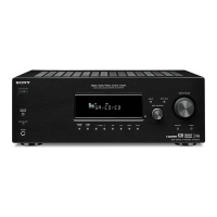
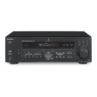
Photo: Black type
Question and Answer IconNeed help?

Do you have a question about the Sony STR DE197 - AV Receiver and is the answer not in the manual?

Sony STR DE197 - AV Receiver Specifications

General IconGeneral
Impedance8 ohms
TunerAM/FM
Total Harmonic Distortion0.09%
Preset Stations30
Power Output100 watts per channel into 8 ohms (stereo)
Frequency Response10Hz to 50kHz
Inputs4 audio
Outputs1 Headphone Jack
Dimensions430 x 145 x 290mm
Surround Sound FormatsDolby Pro Logic

Summary

AUDIO POWER SPECIFICATIONS

Power Output and Total Harmonic Distortion

Details power output and THD for US models with 8-ohm loads.

Amplifier Section Power Output

Specifies power output for US, CND, and AEP models.

SPECIFICATIONS

Analog Outputs

Specifies voltage and impedance for analog audio outputs.

FM Tuner Section Details

Lists tuning range, sensitivity, S/N, distortion, selectivity, and separation.

Analog Inputs and Frequency Response

Details sensitivity, S/N, and frequency response for analog inputs.

AM Tuner Section

AM Tuner Specifications

Covers tuning range, antenna, IF, sensitivity, S/N, distortion, and selectivity.

General Specifications

Power, Dimensions, and Accessories

Lists power consumption, requirements, dimensions, mass, and accessories.

Safety Check-Out

AC Leakage Test Procedure

Explains AC leakage testing procedures and limits.

General Information

Main Unit and Remote Overview

Refers to the main unit and remote button descriptions.

Disassembly Procedures

Case, Front Panel, Back Panel, and Main Board Disassembly

Instructions for disassembling the case, front panel, back panel, and main board.

Test Modes

Fluorescent Tube, Auto-Betical, AM Tuning, and Software Version Tests

Details various test modes including tube test, auto-betical scan, AM tuning selection, and software version display.

Diagrams and Schematics

IC Pin Descriptions and Board Locations

Details IC pin configurations and illustrates circuit board locations.

Block Diagrams

Block diagrams for the main and power sections.

Printed Wiring Boards

Printed wiring board layouts for main and panel sections.

Schematic Diagrams

Schematic diagrams for main and panel sections.

IC Block Diagrams

Block diagrams for integrated circuits.

Exploded Views

Case, Front Panel, and Chassis Section Views

Exploded views of the case, front panel, and chassis sections.

Electrical Parts List

Remote Control Operation

Remote Usage: Before, Batteries, and Button Functions

Covers pre-use checks, battery insertion, and remote button functions.

Revision History

Related product manuals