EasyManua.ls Logo

Sony STR-K7200 - Av Receiver Component User Manual

Sony STR-K7200 - Av Receiver Component
84 pages
To Next Page IconTo Next Page
Page #1 background imageLoading...
Page #1 background image
SERVICE MANUAL
Sony Corporation
Audio Business Gourp
Published by Sony Techno Create Corporation
STR-K7200
SPECIFICATIONS
MULTI CHANNEL AV RECEIVER
9-887-947-01
2008B05-1
©
2008.02
US Model
Ver. 1.0 2008.02
STR-K7200 is the receiver section in HT-7200DH.
This receiver incorporates Dolby* Digital and Pro Logic Surround and the DTS** Digital Surround System.
* Manufactured under license from Dolby Laboratories. Dolby, Pro Logic, and the double-D symbol are
trademarks of Dolby Laboratories.
** Manufactured under license under U.S. Patent #’s: 5,451,942; 5,956,674; 5,974,380; 5,978,762; 6,487,535
& other U.S. and worldwide patents issued & pending. DTS and DTS Digital Surround are registered
trademarks and the DTS logos and Symbol are trademarks of DTS, Inc. © 1996-2007 DTS, Inc.
All Rights Reserved.
This receiver incorporates High-Definition Multimedia Interface (HDMI
TM) technology.HDMI, the HDMI logo
and High-Definition Multimedia Interface are trademarks or registered trademarks of HDMI Licensing LLC.
The XM name and related logo are registered trademarks of XM Satellite Radio Inc. All rights reserved.
“x.v.Color” and “x.v.Color” logo are trademarks of Sony Corporation.
“BRAVIA” and are trademarks of Sony Corporation.
AUDIO POWER
SPECIFICATIONS
POWER OUTPUT AND TOTAL
HARMONIC DISTORTION:
With 6 ohm loads, both channels driven, from
120 – 20,000 Hz; rated 90 watts per channel
minimum RMS power, with no more than 1%
total harmonic distortion from 250 milliwatts
to rated output.
Amplifier section
Power Output
1)
Stereo mode (rated)
(6 ohms 1
kHz, THD 1%)
90 W + 90 W
Surround mode (reference)
(6 ohms 1 kHz
, THD 10%)
RMS Output
2)
FRONT: 140 W
per channel
CENTER: 140 W
SURROUND: 140 W
per channel
1)
Measured under 120 V AC, 60 Hz
2)
Reference power output for front, center and
surround speakers. Depending on the sound field
settings and the source, there may be no sound
output.
Inputs
Analog
Sensitivity: 800 mV/
50 kohms
Digital (Coaxial) Impedance: 75 ohms
Outputs (Analog)
AUDIO OUT Voltage: 800 mV/
10 kohms
SUB WOOFER Voltage: 2 V/1 kohm
Tone
Gain levels ±6 dB, 1 dB step
Reproduction frequency range
28 – 20,000 Hz
FM tuner section
Tuning range 87.5 – 108.0 MHz
Antenna FM wire antenna
Antenna terminals 75 ohms, unbalanced
Intermediate frequency
10.7 MHz
AM tuner section
Tuning range
With 10-kHz tuning scale:
530 – 1,710 kHz
3)
With 9-kHz tuning scale:
531 – 1,710 kHz
3)
Antenna Loop antenna
Intermediate frequency
450 kHz
3)
You can change the AM tuning scale to 9 kHz or
10 kHz. After tuning in any AM station, turn off
the receiver. While holding down TUNING
MODE, press ?/1. All preset stations will be
erased when you change the tuning scale. To reset
the scale to 10 kHz (or 9 kHz), repeat the
procedure.
Video section
Inputs/Outputs
Video: 1 Vp-p, 75 ohms
COMPONENT VIDEO:
Y: 1 Vp-p, 75 ohms
P
B/CB: 0.7 Vp-p, 75 ohms
P
R/CR: 0.7 Vp-p, 75 ohms
80 MHz HD Pass Through
– Continued on next page –

Table of Contents

Question and Answer IconNeed help?

Do you have a question about the Sony STR-K7200 - Av Receiver Component and is the answer not in the manual?

Sony STR-K7200 - Av Receiver Component Specifications

General IconGeneral
BrandSony
ModelSTR-K7200 - Av Receiver Component
CategoryReceiver
LanguageEnglish

Summary

Receiver Specifications

Audio Power and Technical Specifications

Details on output power, harmonic distortion, tuning, inputs, outputs, and video specs.

Servicing and Safety Information

Safety Checks and Component Notes

Procedures for safety checks, leakage tests, and component replacement warnings.

Servicing Notes

Unleaded Solder and Component Replacement

Guidelines for unleaded solder and specific component replacement warnings.

General Information and Front Panel

Front Panel Controls and Functions

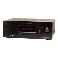
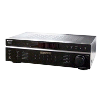
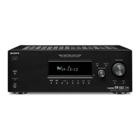
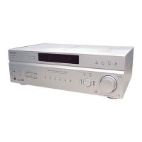
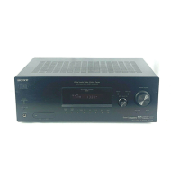
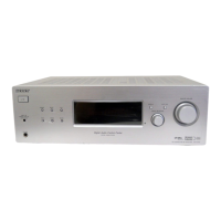
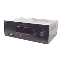
Detailed explanation of the function of each control on the receiver's front panel.

Display Indicators

Display Indicator Functions

Explanation of the various indicators that light up on the receiver's display.

Rear Panel Connections

Rear Panel Connection Overview

Details on digital, antenna, component, audio, video, speaker, and DMPORT connections.

Remote Commander Operations

Remote Commander Button Functions

Explanation of how to use the remote commander for basic operations.

Disassembly Procedures

Disassembly Flow and Case Removal

Outlines disassembly sequence and instructions for removing the outer case.

Block Assembly Disassembly

Procedures for disassembling the back panel and front panel assemblies.

Main Block and Main Board Disassembly

Instructions for accessing and removing the main internal blocks and the main board.

Test Modes

Various Test Modes and Procedures

Instructions for FL Check, Key Check, Swap All, Shipment, Version Check, and DCAC Factory Test modes.

Electrical Checks

FM Auto Stop Check Procedure

Method for verifying FM tuner's automatic scanning stop function.

Diagrams

Block Diagrams

Overview of signal flow for the Main section.

Printed Wiring Boards

Component placement diagram for the MAIN board's component side.

Schematic Diagrams

Detailed circuit diagram for the MAIN board, covering amplifier and related sections.

IC Block Diagrams

IC Block Diagrams for Main and Digital AB Boards

Visual representations of the internal structure of key ICs on Main and Digital AB boards.

IC Pin Function Descriptions

Digital AB Board IC Pin Functions

Comprehensive list of pin functions for ICs on the DIGITAL AB board.

HDMI Board IC Pin Functions

Detailed pin functions for ICs used in the HDMI circuitry.

Exploded Views

Front Panel Section Exploded View

Illustrated breakdown of the front panel assembly and its parts.

Back Panel Section Exploded View

Diagram showing the assembly of the back panel and rear components.

Main Section Exploded View

Illustrated view of the main internal chassis and components for part identification.

Electrical Parts List

DCAC and DCDC Converter Parts List

List of electrical components for the DCAC and DCDC converter boards.

DIGITAL AB Board Parts List

List of resistors, capacitors, and connectors for the DIGITAL AB board.

HDMI Board Parts List

Electrical components for the HDMI board, including resistors and capacitors.

XM Board Parts List

Parts list for the XM board, including resistors and miscellaneous items.

Revision History

Document Version Information

Details on the manual's version number, date of issue, and revision status.

Related product manuals