65
STR-K7200
SECTION 7
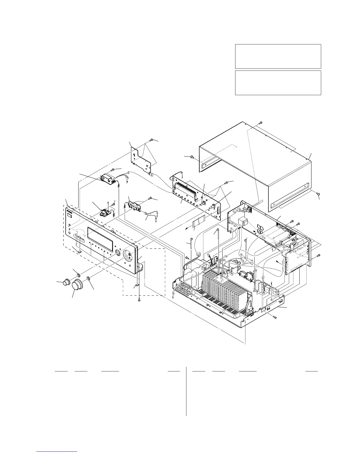
EXPLODED VIEWS
1 2-661-142-01 VOLUME KNOB
2 X-2190-020-1 KNOB MENU ASSY
3 X-2187-665-1 FRONT PANEL ASSY
4 4-977-358-01 CUSHION
5 3-087-053-01 +BVTP2.6 (3CR)
6 A-1433-584-A DISPLAY BOARD, COMPLETE
7 3-701-748-00 CLAMP
8 2-580-630-01 SCREW, +BVST 4X8
9 3-285-693-11 CASE
10 1-828-994-11 WIRE (FLAT TYPE) (17 CORE)
RV101 1-418-817-31 ENCODER, ROTARY (INPUT SELECTOR)
RV102 1-418-725-41 ENCODER, ROTARY (12 TYPE)
(MASTER VOLUME)
#1 7-685-646-79 SCREW +BVTP 3X8 TYPE2 IT-3
Ref. No. Part No. Description Remark Ref. No. Part No. Description Remark
Note:
• -XX and -X mean standardized parts, so
they may have some difference from the
original one.
• Items marked “*” are not stocked since
they are seldom required for routine ser-
vice.
Some delay should be anticipated when
ordering these items.
• The mechanical parts with no reference
number in the exploded views are not sup-
plied.
• Color Indication of Appearance Parts Ex-
ample:
KNOB, BALANCE (WHITE) . . . (RED)
R R
Parts Color Cabinet’s Color
The components identifi ed by mark 0
or dotted line with mark 0 are critical for
safety.
Replace only with part number specifi ed.
7-1. FRONT PANEL SECTION
#
"
$
%
"
&
'
'
#
%
&
$
#1
#1
#1
#1
#1
#1
#1
3
2
1
4
4
5
5
5
5
6
8
5
7
7
7
8
9
supplied with
RV101
supplied with
RV102
not supplied
not
supplied
not supplied
(HEADPHONE
board)
not supplied
(VIDEO 2 board)
not supplied
(DCAC board)
not supplied
(POWER board)
RV101
RV102
back panel section
main section
10
The components identifi ed by mark 9 con-
tain confi dential information.
Strictly follow the instructions whenever the
components are repaired and/or replaced.





 To Next Page