Do you have a question about the Sony DG510 - STR AV Receiver and is the answer not in the manual?
Details power output and THD for US models with 8-ohm loads, driven by both channels.
Lists RMS output power, stereo mode, and surround mode power for US/CND models.
Details power requirements, consumption, dimensions, and mass for different regions.
Lists accessories included with the receiver and common abbreviations used in the manual.
Covers tuning range, antenna, and intermediate frequency for FM and AM tuners.
Lists specific video input and output types and their parameters.
Details AC leakage testing procedures and limits for US models to ensure safety.
Provides part numbers for different models based on their back panel identification.
Highlights critical components identified by marks for safe operation and replacement instructions.
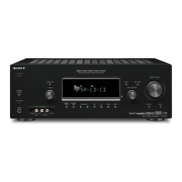
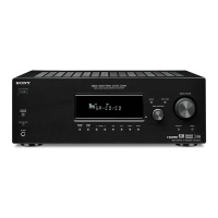
Identifies and describes the function of each control and connector on the front panel.
Explains the meaning of various indicators that light up on the receiver's display.
Details the purpose and connections for various input/output sections on the rear panel.
Explains the function of each button on the remote commander for controlling the receiver and other components.
Step-by-step instructions and diagrams for safely removing the main case of the receiver.
Provides instructions and diagrams for disassembling the front panel assembly.
Details the procedure and diagrams for disassembling the back panel section of the receiver.
Instructions and illustrations for removing the digital circuit board.
Steps and diagrams for disassembling and removing the main circuit board.
Details the process and diagrams for removing the standby power supply board.
Explains how to select between 9 kHz and 10 kHz steps for AM tuning.
Details the procedure to test all segments of the vacuum fluorescent display.
Covers modes for checking buttons, swapping signals, resetting presets, and DCAC factory tests.
Outlines methods for checking DCAC DSP data lines and the DCAC board using test tones.
Details the steps to verify FM auto stop functionality using a signal generator.
Illustrates the physical location of all major circuit boards within the receiver unit.
Illustrates the block diagram showing the signal flow for the tuner and audio processing sections.
Presents the block diagram detailing the processing and signal paths within the digital audio section.
Shows the block diagram for the video signal selection and processing paths.
Illustrates the block diagram for the HDMI signal switching functionality.
Shows the block diagram for handling key inputs and driving the front panel display.
Presents the block diagram illustrating the power supply, driver, and amplifier stages.
Displays common notes for diagrams and specific waveforms for the digital board ICs.
Shows the printed wiring board layout for the main section and lists semiconductor component locations.
Provides the first part of the main board schematic diagram, detailing connections and components.
Continues the main board schematic diagram, showing the second part of the circuit connections.
Shows the printed wiring board layout for the digital section (Side A) and lists semiconductor locations.
Displays the printed wiring board layout for the digital section (Side B) and lists semiconductor locations.
Provides the first part of the digital board schematic diagram.
Presents the second part of the digital board schematic diagram.
Shows the third part of the digital board schematic diagram.
Provides the final part of the digital board schematic diagram.
Shows the printed wiring board layout for the video section, including connections to other boards.
Presents the schematic diagram for the video board, detailing ICs and connections.
Shows the printed wiring board layout for the HDMI switching section and lists semiconductor locations.
Provides the schematic diagram for the HDMI switching board, detailing ICs and signal paths.
Shows the printed wiring board layout for the center speaker connection.
Displays printed wiring board layouts for the DCAC and power key sections.
Provides schematic diagrams for the DCAC and power key sections.
Shows the printed wiring board layout for the display section, including controls and connections.
Provides the schematic diagram for the display board, illustrating its circuitry and connections.
Shows the printed wiring board layout for the standby power section and lists component locations.
Provides the schematic diagram for the standby board, illustrating power supply circuits.
Illustrates the block diagrams for key ICs used on the main board.
Shows block diagrams for ICs used on the digital board.
Illustrates block diagrams for ICs on digital and video boards.
Shows block diagrams for ICs used on the HDMI switching board.
Lists the pin functions and descriptions for the DSP IC used on the digital board.
Details the pin functions and descriptions for the digital interface IC used on the digital board.
Lists the pin functions and descriptions for the system control IC used on the digital board.
Details pin functions for system control and interface ICs.
Shows an exploded view of the receiver's case and lists the part numbers for case components.
Provides an exploded view of the front panel assembly and lists associated part numbers.
Shows an exploded view of the back panel and lists its components and part numbers.
Displays an exploded view of the receiver's chassis and lists the part numbers for chassis components.
Lists resistors, capacitors, connectors, diodes, and ICs for the DCAC board.
Details resistors, capacitors, connectors, diodes, and ICs for the digital board.
Lists capacitors, connectors, and resistors for the digital board.
Lists diodes, jacks, resistors, and ICs for the digital board.
Lists various resistors used on the digital board with their specifications.
Lists parts for display, ICs, switches, and connectors.
Lists resistors, capacitors, connectors, ICs, and ferrite beads for HDMI SW and headphone sections.
Lists various capacitors used on the main board with their specifications.
Lists capacitors, connectors, diodes, and ICs for the main board.
Details resistors and transistors used on the main board.
Lists transistors and resistors for the main board.
Lists resistors, relays, transformers, and connectors for the main board.
Lists resistors, switches, relays, transformers, capacitors, connectors, diodes, and ICs for power/standby boards.
Details resistors, capacitors, connectors, and ICs for the video board.
Lists resistors, transistors, and transformers for the video section.
Lists standard accessories supplied with the receiver, such as remote commander and manuals.
Provides a record of revisions made to the service manual, including version number, date, and description.
| Brand | Sony |
|---|---|
| Model | DG510 - STR |
| Type | AV Receiver |
| Number of Channels | 5.1 |
| Component Video Inputs | 2 |
| Digital Audio Inputs (Coaxial) | 1 |
| Analog Audio Inputs | 4 |
| Headphone Jack | Yes |
| Tuner | AM/FM |
| Surround Sound Formats | Dolby Digital, DTS |
| Audio Outputs | Subwoofer |
| Video Inputs | HDMI, Component, Composite |
| Video Outputs | HDMI, Component, Composite |